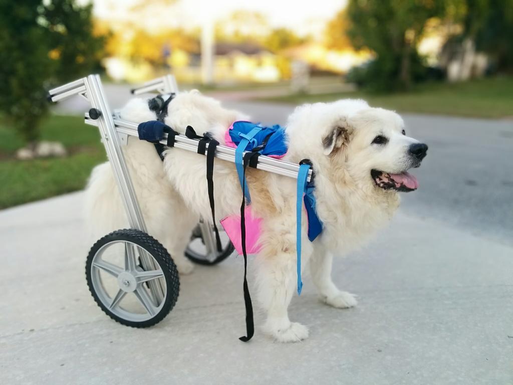

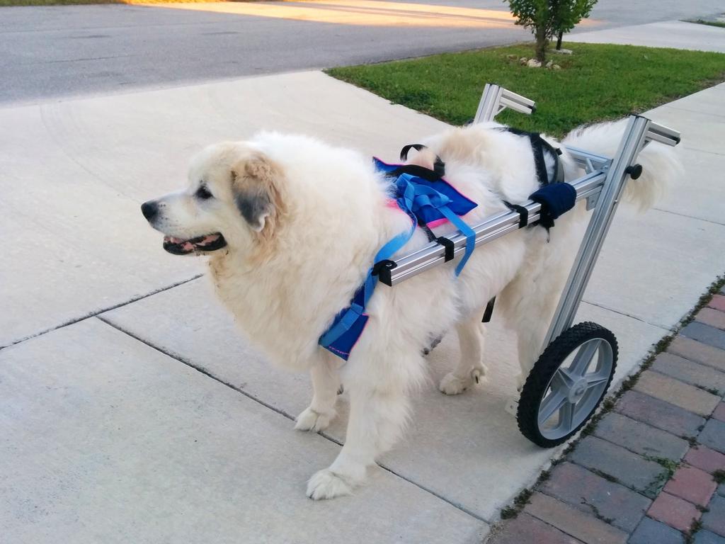
A few weeks ago, my family's Great Pyrenees (Molly) injured her hip. Since then, she's had an increasingly difficult time lifting herself from the ground and supporting her own weight (a hefty 135 lb.). To give her a little more freedom, and to give her back leg a chance to rest, my mom asked if I could make her a 'wheelchair,' which is what I set out to do here. Other dog wheelchairs do exist, but as they are typically bespoke, they can be quite expensive and usually require a lead time of weeks or months.
The Goal
After doing a little research, and taking some quick measurements, I had my quest: build a dog wheelchair large enough to fit Molly's massive frame, hefty enough to support her weight, and adaptable enough to tweak on the fly, using parts that could be obtained in less than a week. Bonus points if it could be built using only hand tools, by the average dog-owner, and on a tight budget. Let's see how I did.
Mockup & Configuration
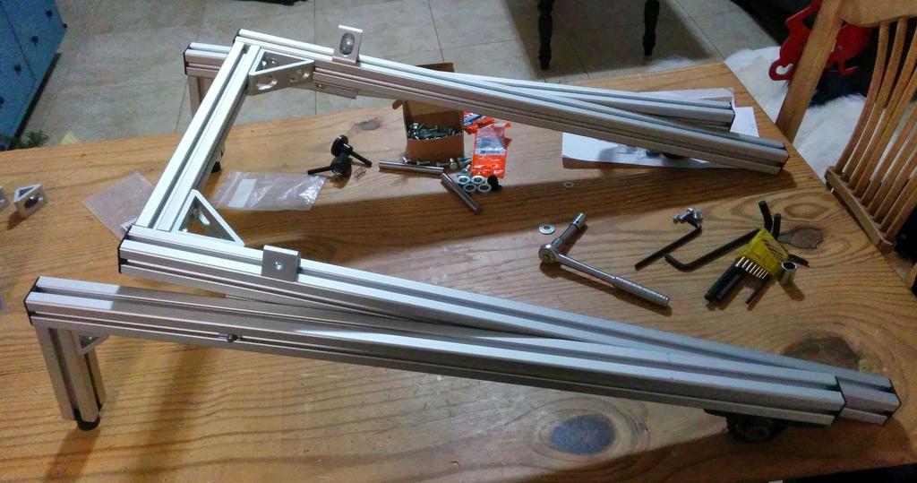
Remember those quick measurements? To make sure that I had enough material, and that the wheelchair could be adapted in the event of something that I didn't foresee, I wanted to buy enough material for it to be 36long, 16
wide (on the inside of the frame), and 30" tall. I also wanted to make it fold, for two reasons:
- if she was comfortable enough to lay down while wearing it, it could be made to take some of the weight off of her hind legs while laying down, and
- if she didn't want to lay down in it, it could be folded and stored away from the shins of unwitting passerby.
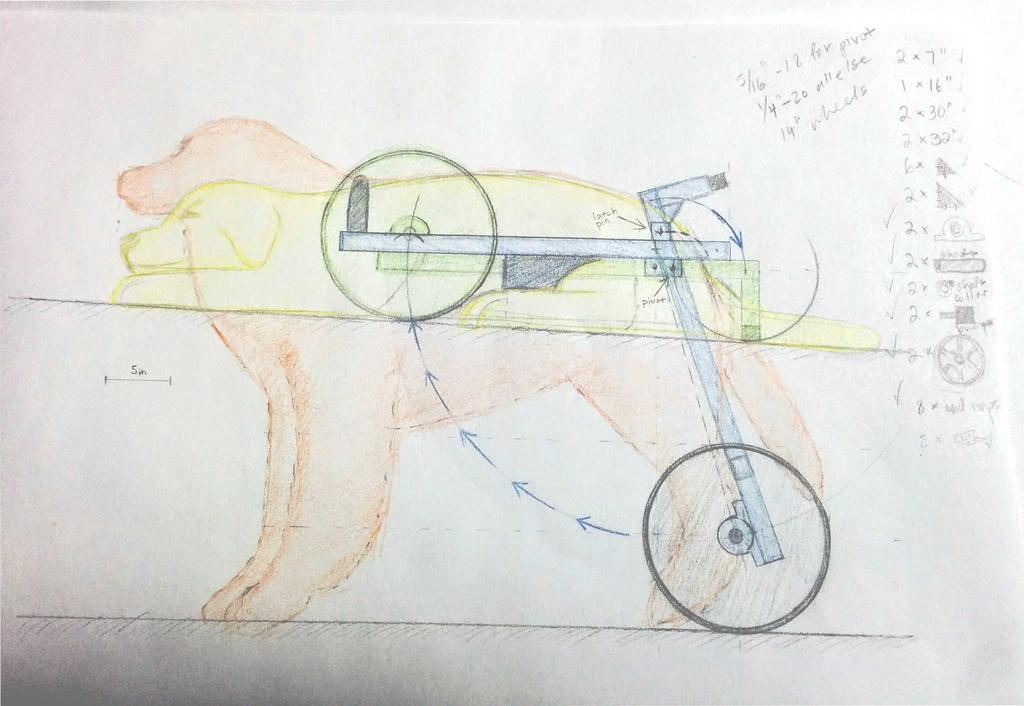
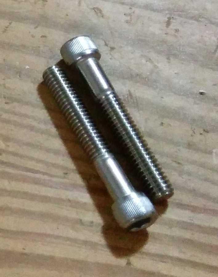
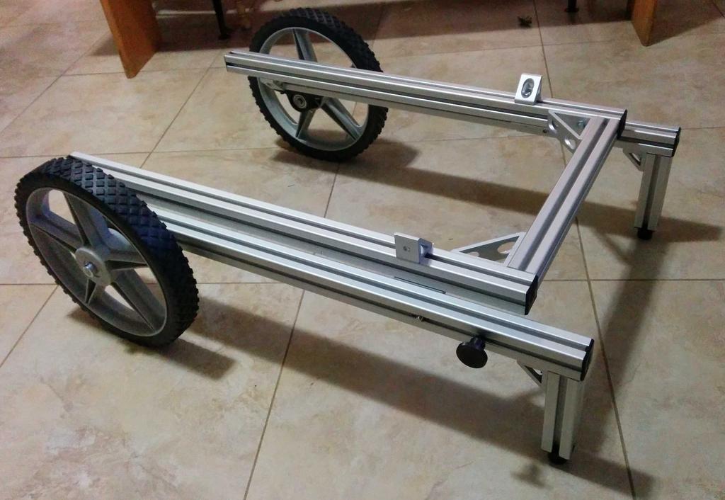
In the configuration above, each leg of the chair hinges on the shoulder (the unthreaded portion) of a 5/16"-18 socket head cap screw, and is locked in-place with another bolt (I'll show this below). As the shear strength of these screws is high enough to not be of concern in this application, intensive calculations justifying their use were not performed.
When the frame is folded and laid horizontally, all of its weight is supported by the wheels (now at the front of the frame) and rubber bumpers that swing down in the back, and it sits parallel to the ground.
Note: As pictured, the wheels are angled backward; in the final configuration, these are angled forward. No changes to the frame must be made to do this, aside from loosening and tightening 2 bolts.
Material Choice (Frame)

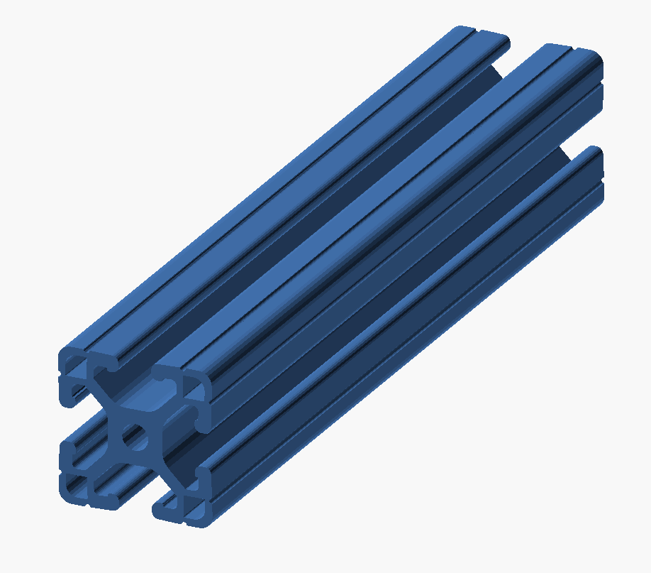
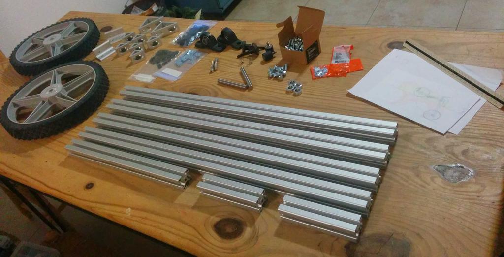
The frame is built from t-slotted aluminum extrusions (from Faztek, model 15QE1515L), with a profile like that shown on the right. This will allow for the desired ease-of-use and adaptability (all fixtures and straps will be secured using t-slot nuts, which fit into the channels on any side of the extrusion, and can be slid and locked into the desired position). These extrusions (along with a wide variety of brackets, supports, and fixtures) are available on Amazon (with free super-saver or Prime shipping options), and thus meet the requirement of being available within one week. Despite being 1.5" wide (and very stiff), these are pretty light, and can be easily cut with a hacksaw.
Parts
Amazon
| Part | Count | Unit Price |
|---|---|---|
Faztek 15QE1515L Aluminum 6063-16 T-Slotted Light Extrusion, 97x 1-1/2x 1-1/2" |
2 | $48.50 |
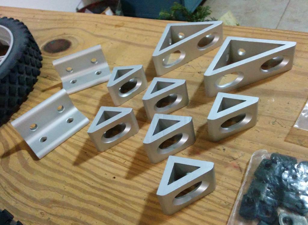
Faztek 15 Series Aluminum 6063-T6 4 Hole Inside Gusset Corner Bracket, 1-19/64Width x 3Length |
2 | $6.88 |
Faztek 15 Series Aluminum 6063-T6 2 Hole Inside Gusset Corner Bracket, 1-19/64Width x 1-1/2Length |
6 | $4.72 |
Faztek 15 Series Aluminum 6063-T6 4 Hole Inside Corner Bracket, 2-51/64Width x 1-1/2Length |
2 | $4.27 |
Faztek 15AC7925 End Cap, 1-1/2Width x 1-1/2Height, For QE Profiles (5 pack) |
2 | $6.45 |
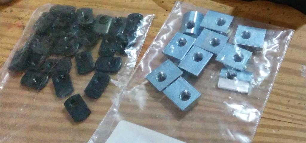
| Faztek 15 Series Carbon Steel Standard T-Nut, 5/8" Width, 5/16-18 Thread (10 pack) | 1 | $9.80 |
| Faztek 15 Series Carbon Steel Economy T-Nut, 1/2" Width, 1/4-20 Thread (25 pack) | 1 | $6.75 |
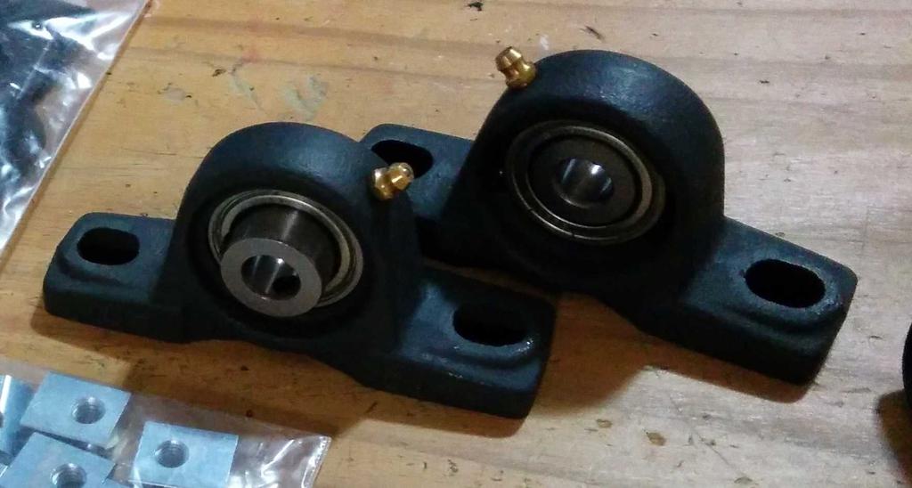
Bore, 1.38Length Through Bore, 1.188" Base To Height |
2 | $15.78 |
| 1475-P 14 x 1.75 Plastic - Spoke Wheel | 2 | $14.21 |
Precision Brand 1/2Precision Shafting, 36Length |
1 | $14.48 |
Climax Metal LC-050 Steel Set Screw Collar, 1/2Bore Size, 7/8OD, with 1/4-20 x 3/16 Set Screw |
4 | $0.81 |
JW Winco 452.1-25-25-5/16-55 Series GN 452.1 Rubber Cylindrical Vibration and Shock Absorption Mount with Threaded Stud, 1Diameter, 1Height |
2 | $5.36 |
JW Winco Steel Knob, Knurled, Threaded Stud, 5/16-18 Thread x 1-3/4Thread Length, 1-1/2" Head Diameter |
2 | $6.69 |
Home Depot
I already had most of the additional hardware used for the wheelchair on hand, though I did buy a few bolts and washers from Home Depot. All of the fasteners needed (aside from what I ordered from Amazon), can be purchased your local hardware store for $10-20. This should include:
| Part | Count |
|---|---|
1/4-20 x 3/4bolts |
10-20 |
5/16-18 x 3/4bolts |
10-20 |
5/16-18 x 2bolts for hinges |
2 |
| 1/4" ID washers | 10-20 |
| 5/16" ID washers | 10-20 |
| Loctite threadlocker or cyanoacrylate glue |
Note: For all of the bolts, use whichever head-style you prefer; I used a mixture of socket-head cap screws (where fixtures might often be adjusted, e.g. where the straps connect to the frame) and standard hex-bolts (for areas that I wouldn't need to adjust, so I wouldn't need to carry a wrench or ratchet around with me). You'll probably save money by buying a box rather than singles (check Amazon if you place an order) if you don't already have what you need.
JoAnn Fabrics
| Part | Count |
|---|---|
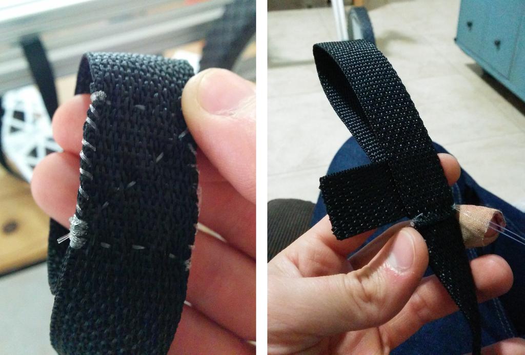
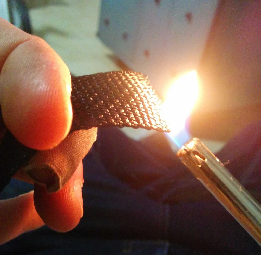
| 1" Polypropylene strapping (this is similar to the strapping on most backpacks, and it's strong, easy to clean, won't appreciably stretch, and the ends can be melted with a lighter to prevent fraying. | 6 yard |
| 1" Parachute buckles | 1 pkg |
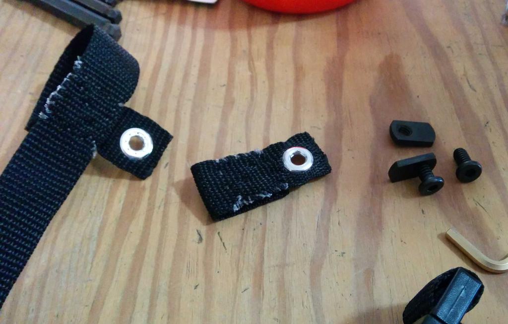
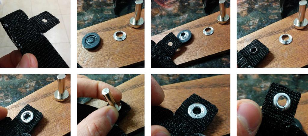
| 1/4" grommets (the package I bought included the tool needed to affix them to the straps) | 1 pkg |
| A needle and strong thread to sew the straps; I actually used 12 lb. test (0.013" diameter) monofilament fishing line instead, as I had a spool of it onhand |


Note: Any fabric store will do, but if you go to JoAnn Fabrics, take as many coupons as you can find. Depending on your cashier, you might be able to use multiple at once (e.g. one 40%-off coupon per item), as long as they have different barcodes. I went on Christmas Eve, and a particularly friendly cashier rang one up for every item that I purchased, netting me 40% off of my entire purchase.
Tools
- Hacksaw (suitable for cutting aluminum; should be fine to medium-toothed), bandsaw, chopsaw, or other means of cutting the aluminum extrusion
- Hammer (for affixing the grommets)
- Ratchet and sockets (size depends on the bolt style you choose)
- Allen keys (size also dependent on your bolts; buy a set of SAE sizes for a few dollars and you should have all that you need)
- Lighter (for melting the ends of cut strapping to prevent fraying)
- Drill and 5/16" drill bit
- 5/16"-18 tap and tap handle (for tapping threads into the ends of the two pieces of aluminum extrusion that attach to the bumpers)
- Measuring tape
Frame Assembly
Cut aluminum extrusion into the following lengths (using the hacksaw), ensuring that all of the ends are as square as possible:
- 4 lengths of 32"
- 1 length of 16
(I later cut this down to 14
as the wheelchair was too wide) - 2 lengths of 7"
Cut two 4
long pieces from the 1/2
steel rod using the hacksaw.Into two of the 32
pieces, drill 5/16
holes 5and 8
from the same end (only one end) of each (the holes should be 3" apart).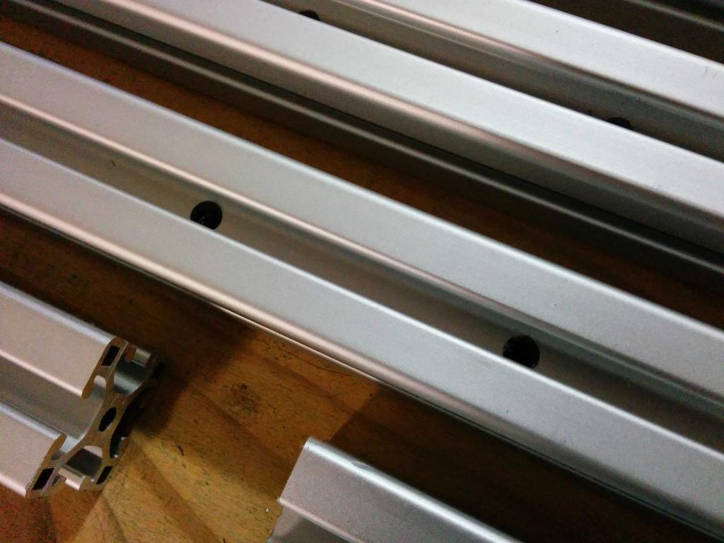
holes drilled (step 3) Tap one end of each of the two 7
pieces of aluminum extrusion using the 5/16
-18 tap, far enough into the end to thread the rubber bumpers completely into the holes. Before threading the bumpers into the ends, place two of the plastic end-caps onto the newly threaded ends of the extrusion, and use the rubber bumpers instead of the plastic plugs to fasten them in place.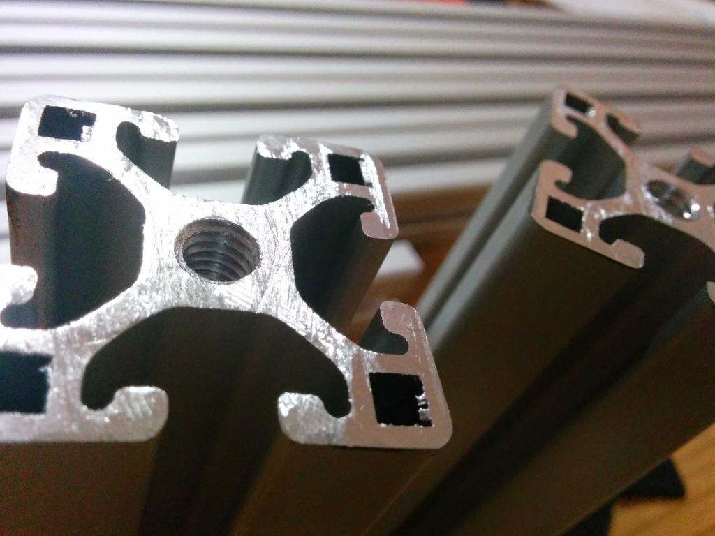
threaded extrusion (step 4) 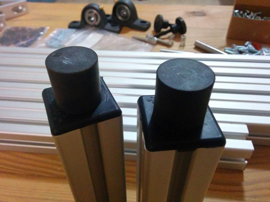
rubber bumpers threaded through end-caps (step 4) Grab two of the smallest angle brackets, and slide 1/4
bolts (with washers) through each of the holes. Begin threading one of the 1/4
t-slot nuts onto each bolt, and slide each bracket onto one of the 7" pieces of extrusion. [All pictured below]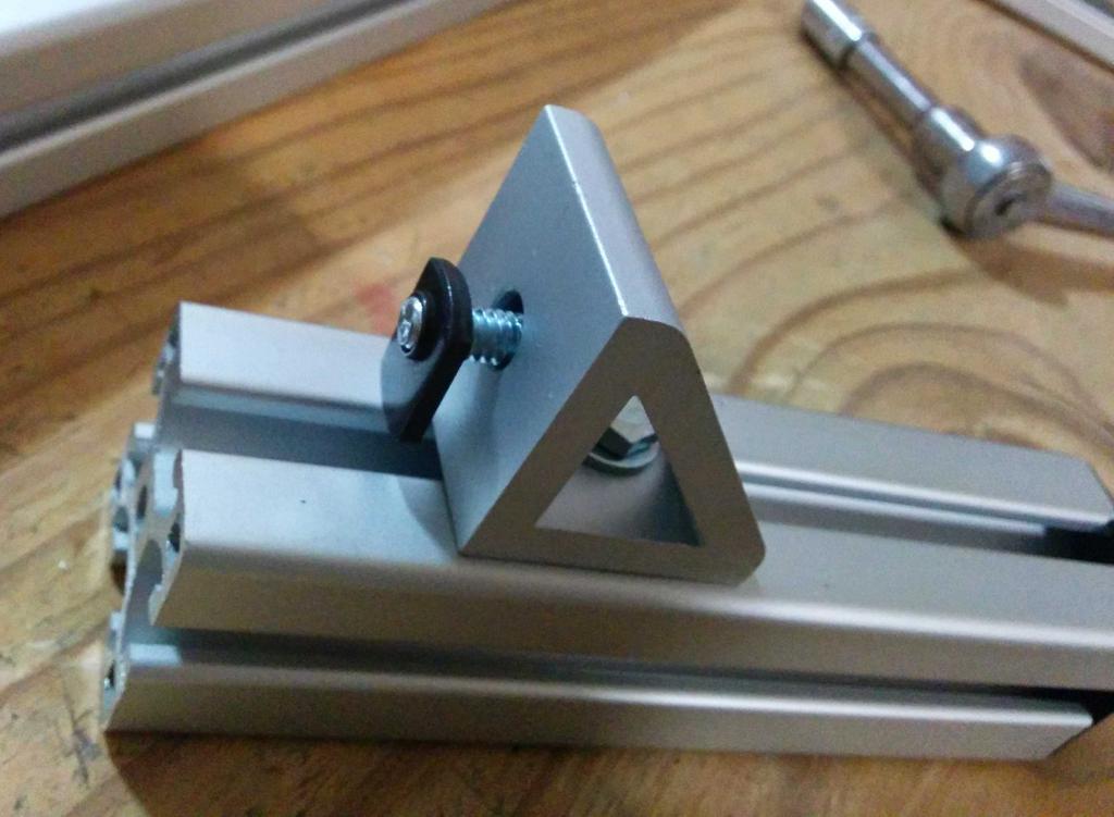
step 5 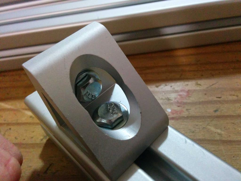
step 5 Continuing from step 5, slide the 32
pieces (with holes drilled) onto the other side of each bracket (onto the ends of the 32
sections with drilled holes, on the ends opposite to the holes, see photo labeledstep 6
for help).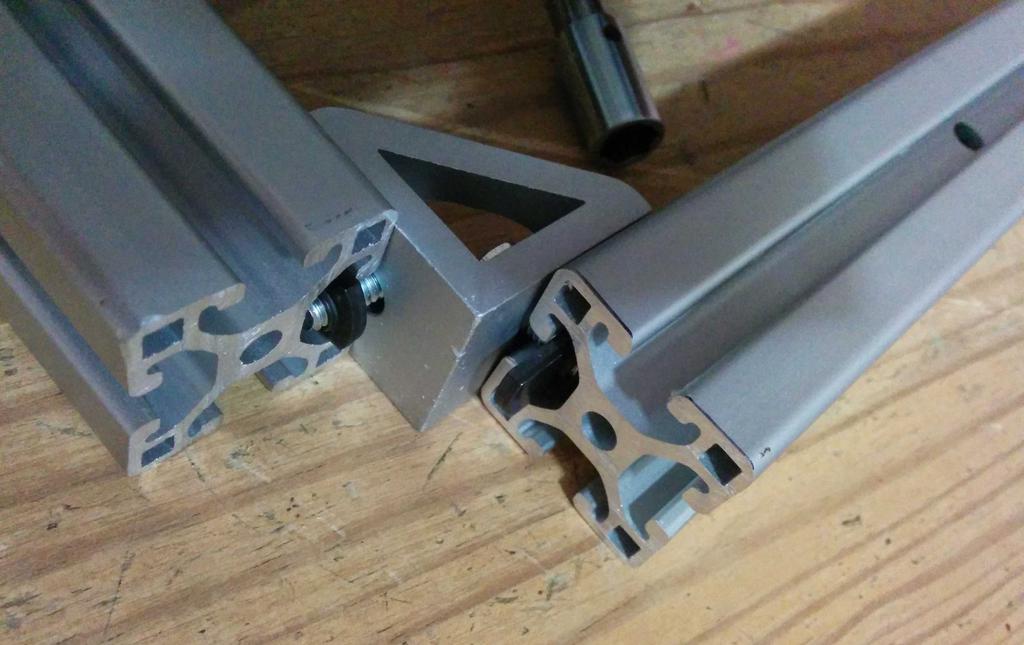
step 6 (orientation hint: see the hole at the top right of the photo?) Affix the pieces from step 6 together as shown in the photo below (the end of the 32" piece should be exposed).
step 7 Take these L-shaped pieces (32
piece + 7
piece + bracket) and place them onto a flat surface so that the 7leg of the L-shape points straight into the air, and attach the bearings (using 5/16
-18 bolts, washers, and t-nuts) to the opposite end of the 32" leg of the L-shape so that they are also pointing into the air.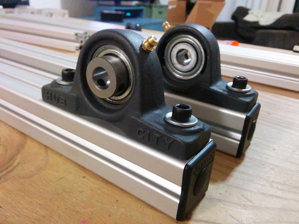
step 8 Take the other two 32
pieces and the two 4-hole 2-51/64
corner brackets, and affix the brackets to the 32pieces of extrusion (using two 5/16
-18 x 3/4bolts each) so that the bracket hole closest to the end of the extrusion is 5
from the end, and so that the pieces are mirror images of each other.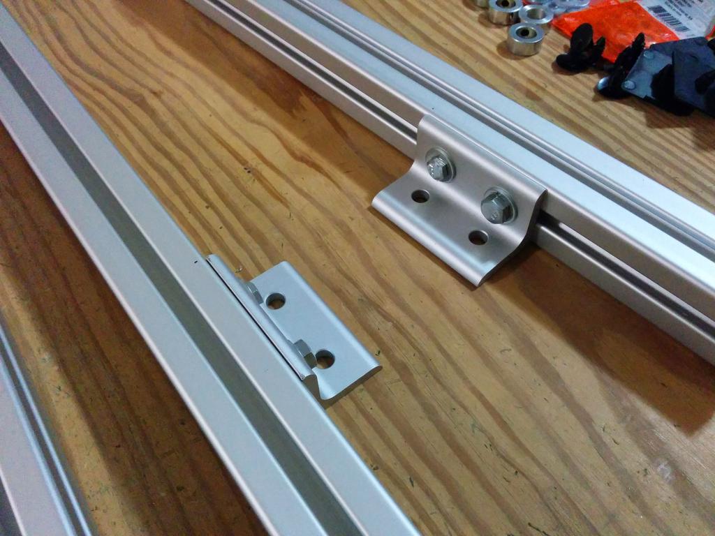
step 9, ends of extrusions immediately out of frame to the right Attach these to the L-shaped pieces assembled earlier, as mirror-images, using the 5/16
-18 x 2
(hinge) bolts, 5/16washers, and four 5/16
t-slotted nuts (two per side of the wheelchair- one on each side of the extrusion). On each side: slide the washer onto the bolt, and pass the bolt through the bracket hole closest to the end of the extrusion. Slide the t-nuts onto the L-shaped piece, on both sides of the extrusion, so that the holes of the t-nuts line up with the one of the two holes drilled earlier (the ones farthest from short-arm of the L), and thread the bolt through these and the hole, applying Loctite to the last t-nut the bolt is threaded-into.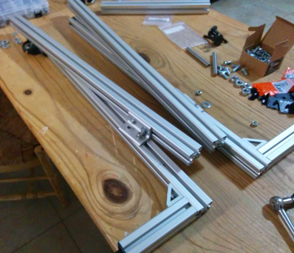
step 10 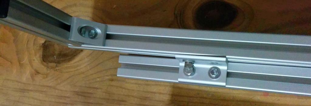
step 10 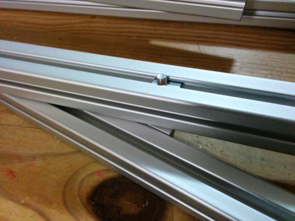
step 10 Continuing with the assembly from step 10, affix a small corner bracket to the opposite side of the extrusion as the 4-hole bracket (with a 5/16
-18 x 3/4
bolt and t-nut) so that the hole in the bracket lines up with the other hole drilled through the extrusion.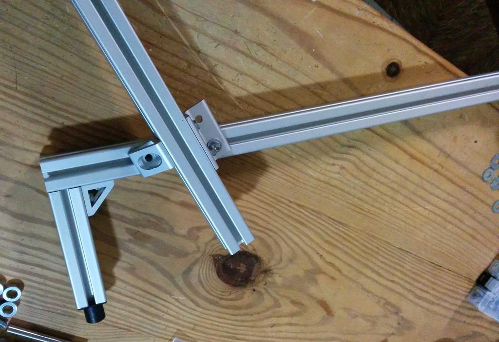
step 11, hole in small bracket aligned with hole in extrusion; in final assembly, small bracket was slid toward end of piece pictured at 11 o'clock, so that it lines-up when rotated to about 1 o'clock Attach 16
piece, as pictured, to the two hinged assemblies using large corner brackets. *Note: After testing, this piece was found to be too wide, and was cut to 14
.*
step 12 Stepping away from the frame for a while, attach a shaft collar onto the end of each of the two 4
segments of 1/2
shaft.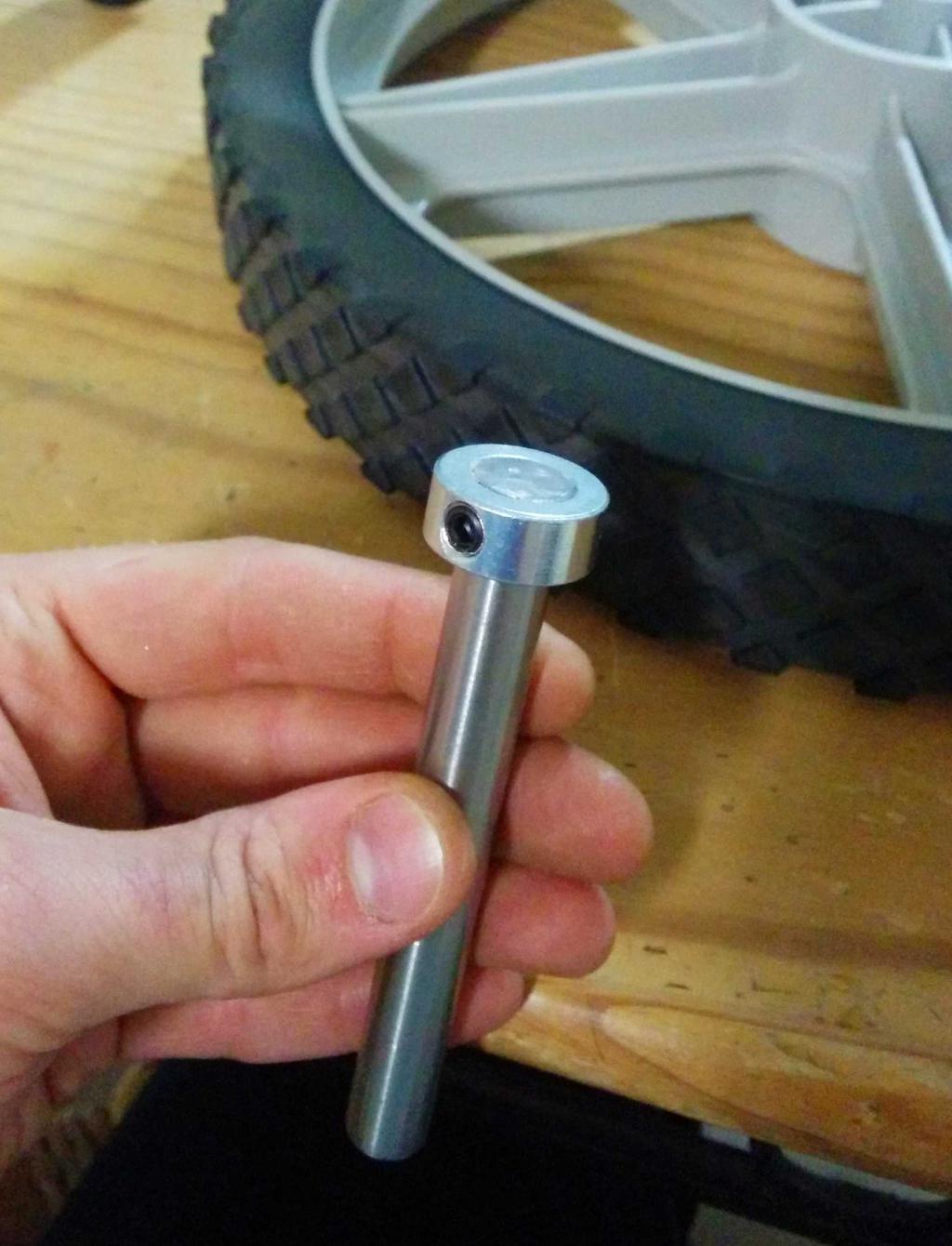
step 13 Slide the wheels onto the shafts, with the shaft collars on the outward-facing side of the wheels.
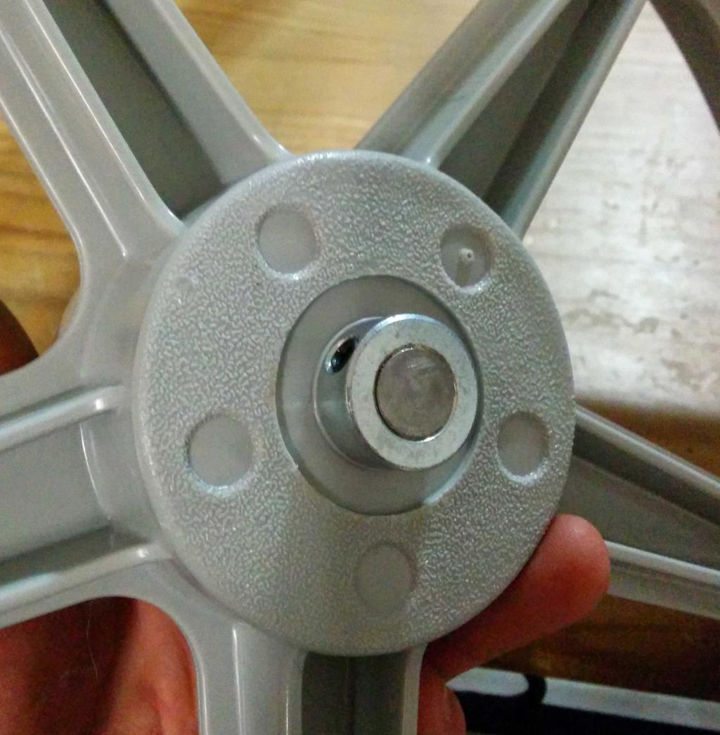
step 14 Flip the wheel over and attach the other shaft collar to the shaft.
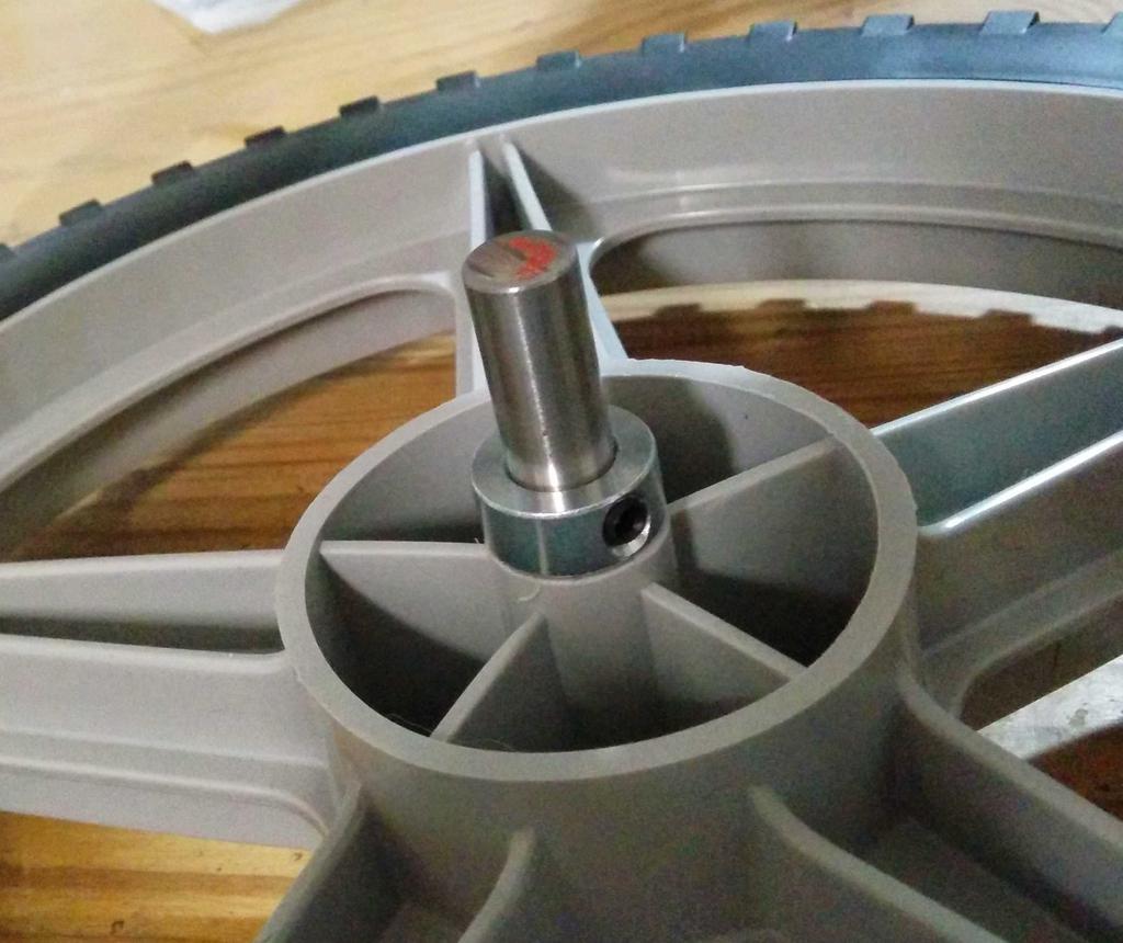
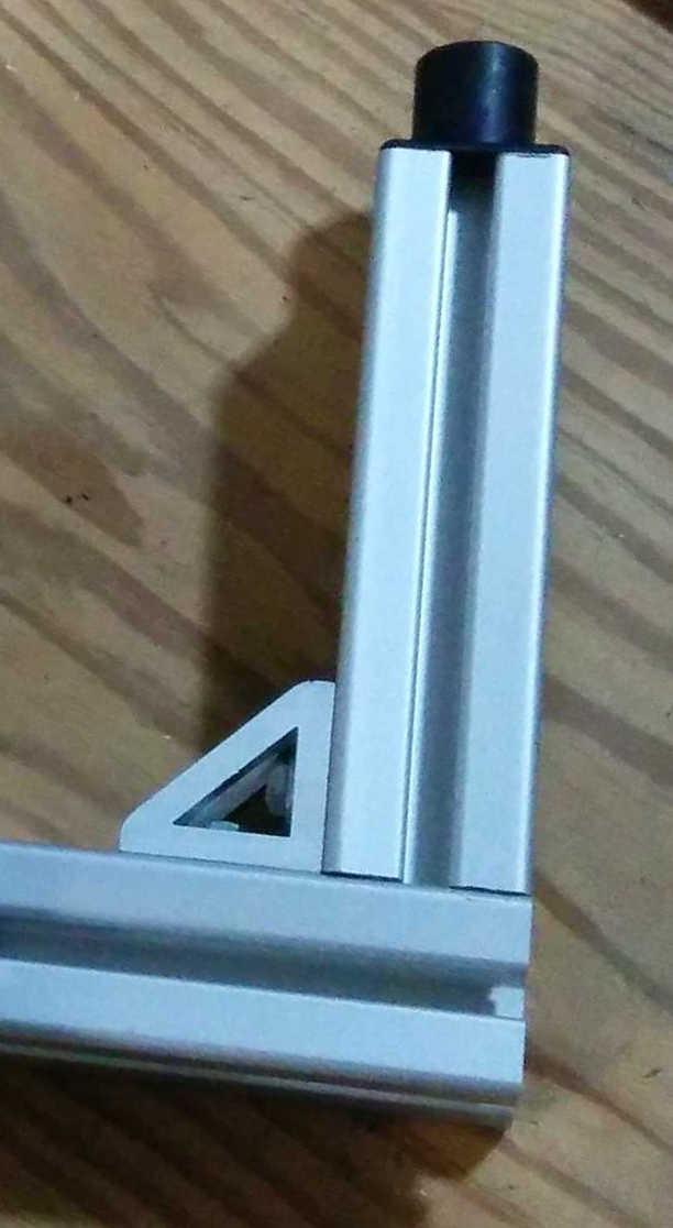
step 15 Slide the shafts into the bearings, so that the wheels are situated on the outside of the frame. Tighten bearing set screws. Fold frame as pictured. Secure final two (small) corner brackets to the swiveling (wheeled) legs, on the inside face of the frame, with the flats side face-up. These will support the u-shaped portion of the frame when folded. Slide the threaded knobs into the unused holes drilled in the L-shaped legs (from the outside of the frame), and thread them through 5/16"-18 t-nuts on the opposite side of the extrusion. These knobs will be tightened into the holes in the corner brackets aligned in step 11 to immobilize the frame when unfolded.
step 16
Straps
Placement
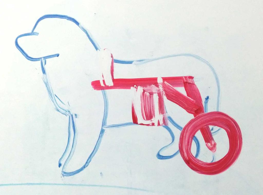
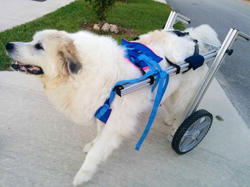
With the frame completed, we must now focus on the straps. Strap placement will depend heavily on how the frame is configured and the weight distribution and size of the dog. One of the great things about the aluminum extrusion is that strap location can be tweaked (slid backward or forward) based on testing to best suit the individual dog. In the original drawings, wheels were angled so that they were placed behind Molly, avoiding the potential stability issues of wheel placed closer to her center of mass, putting more of her weight on her front legs. In this configuration, straps were placed above her shoulders and below her belly. In the final configuration, the wheels were angled forward, supporting more of her weight (and decreasing her turning radius) but requiring more careful strap placement to prevent the frame from tilting backward when she backed up. To account for this, straps were padded under her chest and above her back legs. In the end, this worked well, preventing movement of the frame relative to her body while increasing her maneuverability.
Fastening
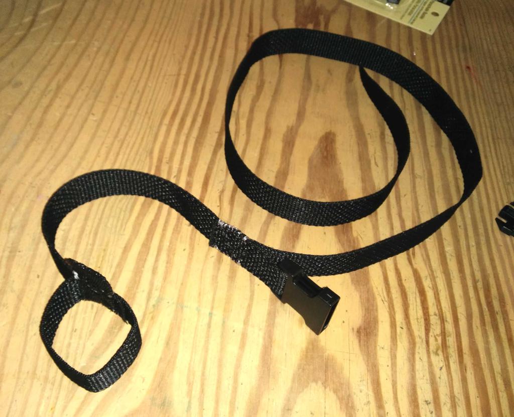
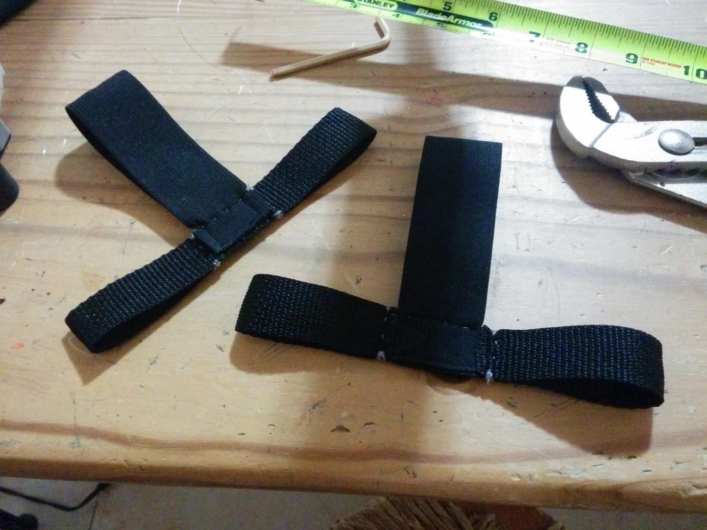
The first set of straps were sewn together by hand using monofilament fishing line, with loops to slide them into place, adjustable buckles to adjust tension, and grommeted tabs for securing them to the frame. To spread her weight over a larger strap area, a harness was sewn together from an old life-vest, purchased at a garage sale for a few dollars; this is the harness shown in the action photos.

Results
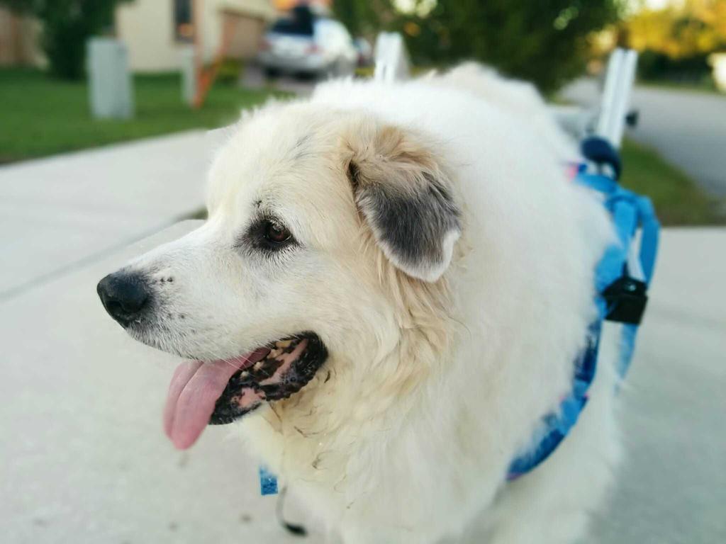
Molly only had the opportunity to take a few walks in her wheelchair, but she definitely appeared to enjoy it, and it helped considerably with mobility. Though I would have liked to make a more few improvements to the design before posting it, as it stands, I hope that it will help others looking for a starting point for a similar project. If you do choose to emulate this design, my main recommendation would be to change the way that the wheels are mounted. Though it wasn't an issue in the short time that we tested it, these specific bearings were designed to be used in pairs (two per shaft). As a result, the shafts onto which the wheels are mounted may deflect (tilting the wheels inward or outward) if subject to enough stress (e.g. hitting a large rock) and begin to rub against the frame.
Enjoy!
To leave a comment below, sign in using Github.