Introduction

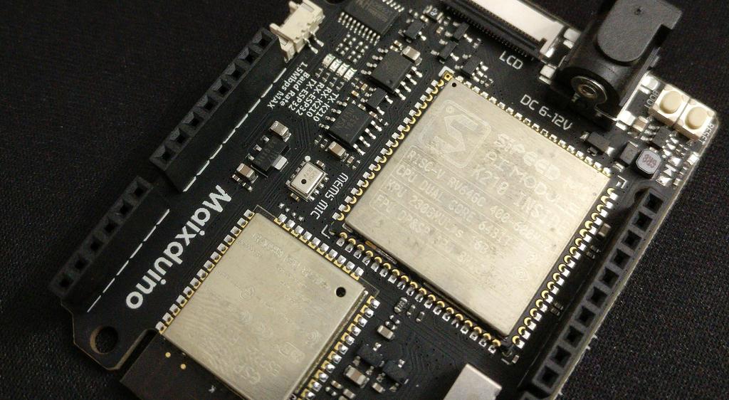
When I first heard about the Sipeed Maixduino AI Kit, I was really excited. At a dime shy of $24, you get a resistive-touch 2.4-inch TFT LCD, OV2640 2 MP camera, and development board built around the Sipeed M1 and ESP32 modules, packing a dual-core, 64-bit 400–800 MHz RISC-V CPU—with FPU, FFT accelerator, audio accelerator (APU), capable CNN neural network accelerator (KPU), and highly-configurable GPIOs—WiFi 802.11 b/g/n and Bluetooth 4.2/BLE provided by the ESP32, on-board MEMs microphone, stereo DAC and power amp, SD-card slot, and USB type C with CH522 USB-TTL. It's programmable in MicroPython (using the MaixPy Firmware) or C/C++, using either the Arduino ecosystem and libraries (using the Maixduino Firmware), FreeRTOS, or the bare-metal SDK.

The real star of the show is the KPU, with performance on the order of 0.25–0.5 TOPS at < 1W power consumption, support for 1x1 and 3x3 convolutions, batch-normalization, pooling, and (arbitrary) activation operations, no direct limits on layer number or layer size, and that is capable of running networks like mobilenet and tiny-YOLOv2 in real-time at QVGA or VGA resolutions. Models can be trained on any system—using Tensorflow, Keras, or any other framework that can be compatibly cross-compiled—and converted and quantized to run on the device using the Kendryte Model Compiler. Models with parameter sets up to 5.9 MiB will run at or above 30 fps; larger networks (up to the flash size) will run more slowly.

With the board in hand, the first thing I wanted to do was get one of the demos working, to get a feel for the software and tooling and to verify that it actually works. Here, I'm describing the steps I took to get that demo, a pre-compiled tiny-YOLOv2 face-detection network (that detects one or many faces) working with the MaixPy firmware. Later on (perhaps in a subsequent post), I'll train one from scratch to run on the device.

Getting Started

Packages

I'm running Ubuntu 19.04, and use python3, pip3, wget, tar, zip, and unzip below. If there's any you don't have installed, the package manager on any modern distribution should have them (if you aren't running some flavor of unix, Google is your friend).

Make and enter the project folder

mkdir maixpy_test
cd maixpy_test

Initialize and source a virtual environment

python3 -m venv ./venv
source ./venv/bin/activate

Install ampy via pip

Ampy is a neat little command-line tool from Adafruit for manipulating files on a MicroPython board over a serial connection, supporting commands like ls, put, get, rm, mkdir, rmdir, reset, and run.

This should install ampy and its dependencies (in my case, adafruit-ampy-1.0.7, click-7.0, pyserial-3.4, and python-dotenv-0.10.3).

pip3 install adafruit-ampy

Download the latest firmware (minimum variant) and face model

Three variants of the MaixPy firmware are available:

  • full – MicroPython + OpenMV API + lvgl (an embedded GUI library) [2.2 MB]
  • no_lvgl – MicroPython + OpenMV API [1.6 MB]
  • minimum – MicroPython alone [833 kB]

Here we're downloading the minimum variant:

mkdir firmware
wget https://github.com/sipeed/MaixPy/releases/download/v0.3.2/maixpy_v0.3.2_minimum.bin -P ./firmware

We'll also download the face detection neural network model for testing (pre-trained Tiny Yolo-v2).

mkdir models
wget https://github.com/sipeed/MaixPy/releases/download/v0.3.2/face_model_at_0x300000.kfpkg -P ./models

Flash the firmware and face model using kflash_gui

Download and extract kflash_gui

wget https://github.com/sipeed/kflash_gui/releases/download/v1.3.2/kflash_gui_v1.3.2_ubuntu16.tar.xz ./
tar -xvf ./kflash_gui_v1.3.2_ubuntu16.tar.xz kflash_gui/
rm ./kflash_gui_v1.3.2_ubuntu16.tar.xz

Flash firmware

We're going to flash two files: maixpy_v0.3.2_minimum.bin and face_model_at_0x300000.kfpkg. To run the GUI:

kflash_gui/kflash_gui

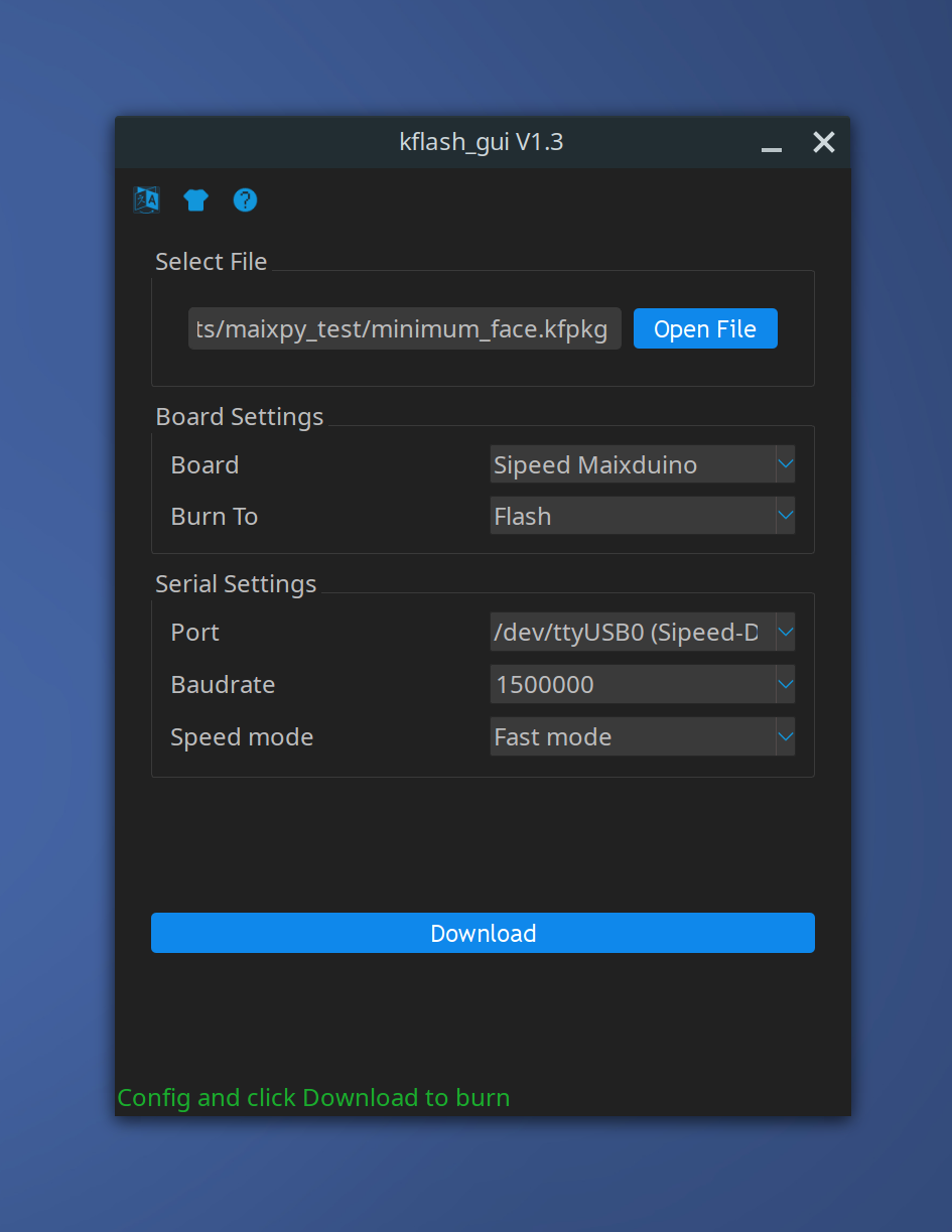
Though /dev/ttyUSB0 (Sipeed-Debug) and /dev/ttyUSB1 (Sipeed-Debug) were both available as ports, only /dev/ttyUSB0 (Sipeed-Debug) worked, so I used that one.

I was unable to select both files using the 'open file' dialog (once I opened the second file, the first one disappeared), so I used the dialog for the first and typed the path of the second myself, making sure to type the offset correctly for the second (0x300000). Next, when trying to flash these, only the first would flash successfully, so I used the 'Pack to kfpkg' option to create a single file, and flashed that instead. This worked fine.

Note: If you get a permission denied error, run the following, reboot, and try again:

Alternatively, you can run kflash_gui with sudo, but this should only be done with software that you absolutely trust.

sudo usermod -a -G dialout $(whoami)

Alternatively, flash the firmware using kflash.py

Though it's a little more work, I prefer this method over using the GUI due to its transparency.

Install kflash.py

pip3 install kflash

As kflash doesn't give the option to flash a file with an address offset, so we'll need to make a .kfpkg file ourselves.

Making a .kfpkg file

Package format

A .kfpkg package is just a .zip file with a custom extension, containing a few specific files:

  • flash-list.jsonjson file describing the files included in our package (more on this below)
  • *.bin formatted firmware file
  • *.* – other files that we'd like to flash (e.g. our model)

Potential snag and workaround

I did not have good luck placing an .kfpkg model file (like the one we downloaded above) directly into another .fkpkg package; the files would flash successfully, but when trying to access the models later on, I would get errors like this:

[MAIXPY]:find ov sensor
[MaixPy] reset | sensor->slv_addr = 60
[MAIXPY]: exit sensor_reset
v=1105938646, flag=1106856192, arch=1185892787, layer len=702694376, mem=1170883809, out cnt=1113997652
err: we only support V3 now, get V1105938646
[MAIXPY]kpu: kpu_model_get_size error -3

One of the things you need to specify when making the flash-list.json file is the memory address where the start of each file should be written, and I suspect that having a .kfpkg within a .kfpkg (each with a flash-list.json and defined addresses) resulted in the model being written somewhere other than where I wanted it to be. As for why this worked in the GUI, I'm not sure, and didn't think it would be worth the time to explore further (but if you're curious enough to dive into the source to find out, go for it).

Thankfully, our model .kfpkg file is, itself, just another zip file, so we can extract it to get the facedetect.kmodel inside, and use that instead.

unzip models/face_model_at_0x300000.kfpkg -d models/

The flash-list.json file

Our .kfpkg package will contain our firmware file, our model, and our flash-list.json. Our flash-list.json will look like this:

flash-list.json

{
  "version": "0.1.0",
  "files": [
    {
      "address": 0,
      "bin": "maixpy_v0.3.2_minimum.bin",
      "sha256Prefix": true
    },
    {
      "address": 0x300000,
      "bin": "facedetect.kmodel",
      "sha256Prefix": false
    }
  ]
}

Let's make our folder, copy our files to it, and create an empty json file:

mkdir minimum_face
cp firmware/maixpy_v0.3.2_minimum.bin minimum_face/
cp models/facedetect.kmodel minimum_face/
touch minimum_face/flash-list.json

Paste the above json into flash-list.json using your preferred editor, and save the file. Next, zip the folder and change the extension:

zip -rj minimum_face.zip minimum_face
mv minimum_face.zip minimum_face.kfpkg

Flashing the .kfpkg

First, determine the device name for your board (running ls /dev/ttyUSB* should give you a list of candidates), and flash the firmware:

kflash -p /dev/ttyUSB0 -B maixduino -b 1500000 minimum_face.kfpkg

Running the face detection test

Download the test file

For simplicity, we'll rename it to test.py.

wget https://raw.githubusercontent.com/sipeed/MaixPy_scripts/master/machine_vision/demo_find_face.py -O test.py

Here's what it looks like:

test.py

import sensor
import image
import lcd
import KPU as kpu

lcd.init()
sensor.reset()
sensor.set_pixformat(sensor.RGB565)
sensor.set_framesize(sensor.QVGA)
sensor.run(1)
task = kpu.load(0x300000) # remember the memory address defined in the json?
## task = kpu.load("/sd/face.kmodel")
anchor = (1.889, 2.5245, 2.9465, 3.94056, 3.99987, 5.3658, 5.155437, 6.92275, 6.718375, 9.01025)
a = kpu.init_yolo2(task, 0.5, 0.3, 5, anchor)
while(True):
    img = sensor.snapshot()
    code = kpu.run_yolo2(task, img)
    if code:
        for i in code:
            print(i)
            a = img.draw_rectangle(i.rect())
    a = lcd.display(img)
a = kpu.deinit(task)

Test it on the device

This will run test.py on the device immediately, without saving it to the device.

ampy --port /dev/ttyUSB0 -d 0.5 run test.py

Success!! In case you're wondering, that microSD I inserted isn't required; I just forgot to remove it.

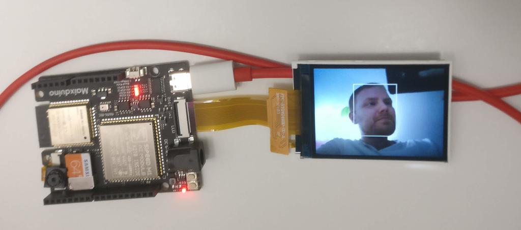
Success!! Now that it works, let's transfer it to the device.

Transfer it to the device

For test.py to load automatically when the device is powered up, we'll need to transfer a copy to the device and create a boot script that loads it.

ampy --port /dev/ttyUSB0 -d 0.5 put test.py /flash/test.py

Make a local backup of the existing boot.py, and replace it with one that will automatically load test.py on boot

First, create the file boot.py and place it in the project folder:

boot.py

with open("test.py") as f:
    exec(f.read())

Next, let's backup the copy of boot.py that was included on device:

ampy --port /dev/ttyUSB0 -d 0.5 get /flash/boot.py > ./backup/boot.py

and replace it with our new one:

ampy --port /dev/ttyUSB0 -d 0.5 put boot.py /flash/boot.py

To check whether this worked, I unplugged it from the computer and plugged it into a powerbank.
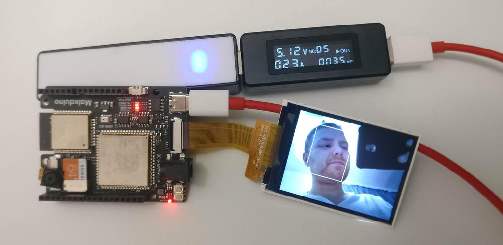
Running on a battery.

Great!

Closing

Here, I took a first look at the Maixduino kit, got one of the demos working, and learned a little about the toolchain. In general, I was impressed. The documentation is reasonably good, albeit a bit rough at times, but the hardware seems capable. Any points lost in documentation are gained back by its use of open source software (making it easier to find answers than otherwise) and in that Seeed Studio has built a number of other products around the same module (suggesting a commitment to the product line).

It's definitely worth checking out!

Product Pages

Documentation

Software

Have something to say? Leave a comment.

Build the world you want to live in

A call to action

No one else in the world has a wallet, keyholder, or watchband like mine. I know that because I made them.

We increasingly live in a world filled with constructed objects; ones made by people, for people. And typically not by those who coexist with them. In the sense that every human is a person, some might think of this as the personalization of our world, but in the sense that we are all individuals, with a spectrum of concerns, priorities, and needs, it is impersonal too.

As our objects are typically not made for us specifically, but for who we are presumed to be demographically, they will never be quite right for us unless we make them so. Personalizing our objects to better suit our own needs is empowering; creating them ourselves, precisely for ourselves, even more so.

You may say 'I could never do that,' or 'I don't have time for that.' But if you have ever changed the wallpaper on your computer or your ringtone (you might even have chosen not to use one at all), or if you have ever painted a room, you've already done it! You may say 'I like the things I buy, and I buy what I like,' or 'I'm no expert, the person who designed this knows better.' But you aren't the average person they designed things for—you are you. And nobody knows you better than you, even if you don't know it yet.

So go out and make. Because your world is what you make of it, whether you make it or not.

Have something to say? Leave a comment.

Extruded Aluminum 3D Printer

In this post, I wanted to put together an overview of the 3D printer that I built around four years ago, including a brief discussion of some of the improvements I've made to it since.

Before I built this printer, I had a Printrbot LC, which I bought as a kit in January of 2013. I used that printer almost daily for about two years, but began to outgrow its capabilities. Eventually, while in storage for a move, it was damaged, and I took that as an opportunity to build a new one, a better one—one of my own design.

The Goal

In short, I wanted to build a printer that could:

  • print larger objects (while the LC had a print area of about 150 x 150 x 150 mm, I was aiming for around 300 x 300 x 300 mm),
  • print a broader range of filaments, at a wider range of temperatures (requiring an all-metal hotend),
  • print more quickly (requiring greater rigidity), especially given the desire to print larger parts,
  • be upgraded continuously over time,
  • be hacked on and serve as a platform for continual experimentation,
  • be built largely from what I had on hand, without spending too much money up front, and
  • be built by hand, without the need for custom machined or (immediate need for) printed parts.

Details

Frame

Much of the frame of this printer was built using 1.5aluminum extrusion, repurposed from my previous dog wheelchair build, and 1/8-thick 1" aluminum angle stock, purchased from Home Depot.

Aluminum for frame and gantry: 1/8 in. thick, 1 in. aluminum angle and 1.5 in. aluminum extrusion

I didn't buy any additional aluminum extrusion when building this printer; instead, I measured out what I had from building the wheelchair (along with any that I had left-over) and planned the build around that. Given the material constraints—and that this would be a one-off build—I figured it would be easier to plan on paper than in CAD.

X and Y Axes

Topology

As I was curious about the practical difference between the H-bot and CoreXY topology for moving the gantry (despite already understanding the technical advantages of CoreXY)—and as I could build the printer to require only minimal changes to swap between the two (swapping one belt for two, and re-routing them slightly)—I initially built the printer as an H-bot, and switched to CoreXY after a few days and a few prints. While there wasn't much of a difference at low print and travel speeds, there was slight (but visible) torsion of the gantry at very high speeds with the H-bot topology, even on this fairly rigid frame, which I was not comfortable with.

Thus, this printer uses the CoreXY topology, with GT2 belts and timing pulleys.

printer belt paths; on right, belts are twisted to prevent collision

Pulleys

Any free-turning pulleys (i.e. those not mounted to stepper motor shafts) turn on bushings cut from Delrin tubing (slightly longer than the pulleys), themselves fastened to the frame or gantry using cap-screws (okay, two are actually pan screws). As installed, the pulleys turn with very little friction and no appreciable eccentricity. Every once in a while, if they start to squeak, I add a drop of oil to them.

CoreXY belt routing

Belts

To fasten belts to the gantry, instead of using some complicated clamp system like I'd seen other printers use, I wrapped the belts around the exposed head of a socket-head cap-screw (tooth-side in), meshed the belt with itself, and used two zip-ties to hold it together.

For the two belt mounts beneath the extruder motor, I used a bit of 4mm-ID Delrin tubing (that began life as a PCB standoff) to elevate the heads enough from the surface of the gantry to support the entire width of belt, whilst the cap-screws are fully tightened. The extruder motor, mounted about a mm above this, ensures that these two belts will never slip upward and detach (the next two figures illustrate this).

affixing a belt to the gantry by wrapping it around the head of a cap screw, meshing it with itself, and zip-tying it together

For the other two mounts (in front of the extruder), a greater length of Delrin tubing is used (as long as the belt is wide), and a small washer is placed above it and the belt to provide the same level security (see figure below).

slip-free belt fastening using nothing more than zip-ties

While some claim that a printer's belts should be tuned like guitar strings, as long as they're reasonably taut, I haven't found that to be necessary. Pulling them hand-tight—with roughly equal tension—and applying a spring-steel belt tensioner to each belt seems plenty adequate to prevent backlash.

belt tensioners

Photos taken of gantry during initial build

X-axis sled with linear bearing mounts and Y-axis rod mounts

X and Y-axes coming together

Mounting hotend to gantry. I used a bowden-compatible hotend with a direct drive extruder for greater freedom in extruder mounting. Because of this, I could, in theory, convert the printer to use a Bowden feed system.

NEMA17 extruder motor mount added to gantry.

Gantry first mounted to the frame

Parts

Count Part
4 500 mm long, 8 mm diameter chrome-plated case-hardened linear rods for X and Y axes (2 each)
6 SCS8UU linear bearing pillow block bearings for gantry
4 SHF8 8 mm rod holders for X and Y axis rods
10 m GT2 belt, 6 mm, fiberglass reinforced
10 GT2 timing pulleys, 20-tooth, 5 mm bore
2 GT2 belt tensioners for 6mm belt

Z Axis

Given the extent of the printbed, I wanted to ensure that it was supported at all four corners. To do this most simply, it meant that I'd need four linear rods and two leadscrews, and that I'd need to be extremely careful not to overconstrain the thing. To that end, once I'd mounted the long linear shield bearings (LMF8LUU) to the printbed sub-platform, I mounted the leadscrews, then loosely mounted the rod holders and rods (with the sub-platform already on the rods), and by successive approximation, slid the sub-platform up and down, over and over, gradually tightening the rod holders to the frame until the sub-platform could slide up and down freely while remaining level.

Leadscrews

Initially, I used M5-threaded rods as leadscrews, coupled to the Z-axis steppers using flex-couplers, and made custom anti-backlash nuts (consisting of two brass nuts, pushed apart by a compressed spring, prevented from rotating independently by a custom housing), as the parts were easier and cheaper to source locally than proper leadscrews. Metric rod was chosen over the (more common) SAE options, so that common layer heights could be achieved using an integer number of stepper-motor steps.

My current setup consists of 8 mm ACME leadscrews, coupled to the Z-axis steppers using flex-couplers (as before) and to the printbed sub-platform using acetal (POM) anti-backlash nuts, with pillow block bearings and thrust bearings placed at the bottom. The thrust bearings were added below the leadscrews to prevent extension of the flex-couplers as a part is printed (and as more weight is placed on the build platform), to maintain consistent layer heights throughout large prints and to wear less on the Z-axis stepper bearings.

Z-axis details; from left to right: Z-axis limit-switch, flex-couplers, anti-backlash nut (front and back), pillow block at bottom of ACME leadscrew (and thrust bearing below it, not visible in photo), linear rod mounts

Parts

Count Part
4 500 mm long, 8 mm diameter chrome-plated case-hardened linear rods for Z-axis
4 LMF8LUU linear shield bearings for printbed
8 SK8 8 mm rod holders for Z axis rods
2 500 mm long, 8 mm diameter ACME Z-axis leadscrews
2 flex-couplers, 5 mm to 8 mm
2 pillow block bearings, 8 mm
2 small thrust bearings
2 acetal (POM) anti-backlash nuts

Motors

Aside from the extruder motor, all of the motors used are Kysan 1124090 NEMA 17 steppers, taken from the old Printrbot. I originally used one of the same for the extruder, but faced the occasional issue with filament jamming, especially at higher print speeds. Changing to a Zyltech 17HD48002H-C5.18 stepper motor (with an integrated 1:5.18 planetary gearbox, and around six times the torque) solved both issues. I've had no issues with stripping either, probably as I was able to further tighten the idler's grip on the filament without stalling the motor.

3D-printed adapter for mounting NEMA 17 stepper with planetary gearbox to a standard NEMA 17 faceplate stepper mount

To be able to mount the geared stepper motor to the same NEMA 17 faceplate mount that I used before, I designed and printed an adapter (you can download it here from Thingiverse). While the motor is fairly heavy for one secured directly to the gantry, I haven't experienced any discernible flexing of the X and Y linear rods, nor any real issues with ringing, though I'm sure I would if I tried to increase the print speed too greatly.

Parts

Count Part
4 Kysan 1124090 NEMA 17 stepper motors (0.54 N-m), one each on the X and Y, and two on the Z
1 Zyltech 17HD48002H-C5.18 NEMA 17 stepper motor with 1:5.18 planetary gearbox (3.1 N-m) for the extruder

Extruder

For the body of the extruder, I used one of the countless permutations of NEMA 17-mount MK8 aluminum direct-drive extruder kits available on Amazon, Ebay, Gearbest, Banggood, or Aliexpress (a picture of the specific one I used can be seen below), but with an 8 mm bore filament drive gear (also pictured below) that I purchased separately after upgrading to a geared extruder motor. Having used an extruder with a hobbed bolt in the past, I vastly prefer the style of both of these filament drive gears to the idea of a hobbed gear; the 8 mm gear used now has sharper teeth than the 5 mm gear I used before (whose teeth have an involute profile), but both grip far better than did the hobbed bolt of old.

From left to right: NEMA 17 faceplate motor mount, large-bore (8 mm) extruder gear, threaded inserts used in aforementioned adapter, direct-drive extruder

To make it easier to print flexible filaments, I constrained the filament path at the outlet of the extruder using a bit of teflon tubing and heatshrink (this keeps a flexible filament from kinking between the extruder gear and outlet). The heatshrink was placed around the teflon tubing to enlarge it, such that it could be securely screwed into the threaded outlet of the extruder body (which was threaded for connection to a press-fitting, meant for use in a Bowden setup). The teflon tubing is only long enough to extend to the top of the heatbreak of the hotend—keeping it far away from the heat, where it might thermally degrade and off-gas (PTFE fumes are no joke)

Constrained filament path using heat-shrink and teflon tubing (which does not extend into the hotend due to concern for thermal degradation). Shown using original extruder motor.

Geared extruder motor, with large-bore filament drive pulley, mounted to gantry.

Hotend

On this printer, I use an E3D clone hotend with a 0.5 mm brass nozzle, screw-in M3 stud thermistor, and 40W cartridge heater. Buying a cheap hotend, I didn't expect to find great suface finish or concentricity between the heatsink and heat break. In reality, there weren't any visible issues, but I did run a small round file up and down the inside of the hotend a few times just to be sure.

Given that I now have another printer with a similar nozzle diameter (0.4 mm)—an Anycubic Kossel Linear Plus Delta, discussed briefly here—I may soon switch this one for a 1 mm nozzle, to print larger parts faster. This should make better use of the large build envelope, and might make printing with flexibles and exotics even easier.

When I built this printer, 3 mm filaments were still more common than 1.75 mm ones, and as I already had several 2.85/3 mm rolls from using the LC, I chose to stick with that size. Nowadays, 1.75 mm filaments are a bit more common, but I've got enough 3 mm filament around to last for a while (and a Kossel that prints 1.75), so I'm in no rush to make the conversion.

To insulate the heat-block, I wrapped it in VersaChem Tiger Patch Muffler and Tailpipe Repair Tape, which self seals in twenty minutes and is resistant to temperatures of greater than 1000 C. I bought it at an autoparts store for around $6, and it works a treat. Before using that, the printer had a little trouble keeping the hotend at temperature when using the part-cooling fan with high-temp filaments, but not anymore. One of the silicone heatblock 'socks' you can buy probably would have also worked, but none that I saw were properly dimensioned to fit my heatblock.

Hotend heat-block insulation using muffler-repair tape

For part cooling, I mounted a squirrel cage fan to the gantry, in front of the hotend, with a custom nozzle. This works well enough, even though the airstream doesn't wrap all the way around the nozzle. Previous attempts at using thin 30 mm or 40 mm square fans were not as successful, as they weren't able the handle the back-pressure caused by restricting the outlet airflow with a nozzle (which is necessary to avoid cooling both the part and the heatblock).

squirrel fan for part cooling

Print Surfaces

When I built this printer, there weren't any reasonably-priced heated beds as large as I wanted, so I made my own. For that, I used 2 panes of borosilicate glass (top and bottom), a single layer of aluminum tape (on the underside of the top pane of glass) for dispersing heat, nichrome wire to generate the heat, kapton tape to hold the nichrome wire in place, 2 silicone baking mats (both placed the nichrome wire, insulating the bottom of the heated bed to direct more of the generated heat heat upward). The silicone baking mats were chosen for their temperature resistance, as was the kapton tape. The length of nichrome wire used, at the time, was chosen to meet some a resistance target at the time of the build (given the linear resistance of the gauge used, desired power output, etc.), but I not longer have those figures. What I do remember is that it heated up quickly and evenly, maintained a set temperature without difficulty, and (like any other heated bed) was easy to automatically calibrate using Marlin PID tuning.

custom heated bed sandwich

Custom heated bed using nichrome wire, high-temperature silicone baking sheets, aluminum tape, and glass. A thermistor is placed at center, but not shown.

I don't use the heated bed very often anymore, as I've had good luck with printing directly onto either 5/16" thick polycarbonate or onto Buildtak-like stickers adhered to sheet magnets (one sheet magnet adhered directly to the subplatform, and a second adhered directly to the Buildtak-like sticker and held magnetically to the first).

The subplatform that I've repeatedly mentioned is a 3/8" thick acrylic light guide plate salvaged from an old flat-screen TV, to which the Z-axis linear bearings and anti-backlash nuts for the Z-axis leadscrews (via a long piece of aluminum angle stock) are mounted. Any printbed used (e.g. the polycarbonate) is clamped directly to that. I never devised a way to level it against the hotend, as the most leveling I've ever had to do entailed slipping a sheet of paper under one edge of the printbed.

Printer Control Board

When the LC was damaged, a portion of the Printrboard went with it. I reworked the board to make use of a few unused AT90USB1286 pins (more for the challenge than out of necessity), remapped them after flashing stock Marlin, and continued to use that board for another two years.

Eventually it failed altogether, so I switched to an MKS Base2, designed around the ATmega2560, with newer DRV8825 stepper drivers (with 1/32 microstepping), and support for dual extruders (if I ever decide to add another) and stock Marlin firmware.

MKS Base2

I hacked together a case for it using the shell of an old CD-ROM drive, a bit of acrylic, a small fan for cooling the stepper drivers and heater FETs, and 3D-printed endcaps. I mounted this at the bottom of the printer, where I could access it without having to move things around.

MKS Base2 in the shell of an old internal CD-ROM drive

Print Server

I control and manage the printer via a local print server (accessible only to the local network) setup using an Orange Pi Zero (the model with 512 MB of RAM) and Octoprint running on Armbian. This is hard-wired to the printer by USB and the modem by ethernet, and is powered by the same UPS as the printer to prevent print interruptions (the power flickers a lot where I'm from).

Orange Pi Zero running Octoprint, with custom 3D printed enclosure

Having a dedicated printer controller makes for a much more pleasant experience than plugging the printer into a computer or printing directly from an SD card. For starters, it allows you to work from your main computer without the worry of hanging a print during periods of high CPU utilization, and allows you to remotely monitor a print from anywhere in the house (even from a cell phone), which is particularly useful if you have a camera connected. Doing so from a single board computer also uses much less energy than would a desktop or laptop (potentially by a few orders of magnitude), and can be more reliable, as the software needn't change often if you're satisfied with how it works.

To help with the remote monitoring, I connected a Sony PS3 Eye camera to the Orange Pi, and printed a custom mount for it. I've never even seen a PS3 in person, but it's hard to argue against a $5 camera of known provenance that is natively supported on Linux, particularly when it's capable of capturing 480p video at 60 Hz with good low-light performance, a wide field-of-view, and an adjustable zoom-lens.

PS3 Eye makes for a great $5 USB camera; works out of the box on Linux

First few prints

One of the nice things about a cartesian printer is that, once you have the firmware properly configured for your hardware, you don't need to worry much about calibration. Aside from extrusion parameters, I never had to do any dimensional calibration with this printer; even the the first several prints were dimensionally accurate and square in all three axes.

The first print. Not bad!

Tips, tricks, and other details

Wire Routing

When routing wires around the frame, I cut short lengths of black spiral cable wrap, wrapped them around the wires I wanted to retain, and pushed them into the nearest channel of the aluminum extrusion. This keeps the wires out of the way (inside the channel), is secure but easily reconfigurable (unlike zip-ties), doesn't require unplugging anything to set up, and works on a range of sizes of aluminum extrusion.

spiral cable wrap is great for retaining wires in the channels of aluminum extrusions

Application of oil for lubrication

For applying small amounts of low-viscosity lubricant, I've found nothing better than a 1 mL syringe and blunted 18 ga needle. It allows you to dispense single drops in tight spaces without making a mess, is easier to keep out of the way than an oil-can, and can be capped to avoid accidentally making a mess.

it's much easier to apply lubricant with a blunted syringe needle than otherwise

Enclosure

The printer currently rests inside of a built-in cabinet. To be able to dampen noise a little while printing, I mounted a small retractable PVC curtain to the shelf above it. So that I could still keep an eye on it while closed, I cut a rectangular window from it and replaced it with clear vinyl.

Additional Photos

Printer, front view, before switching to ACME leadscrews

Printer under construction, before converting to CoreXY

I think that covers most of it! If you have any questions or comments, feel free to post them below or to send me an email.

Have something to say? Leave a comment.