But why?
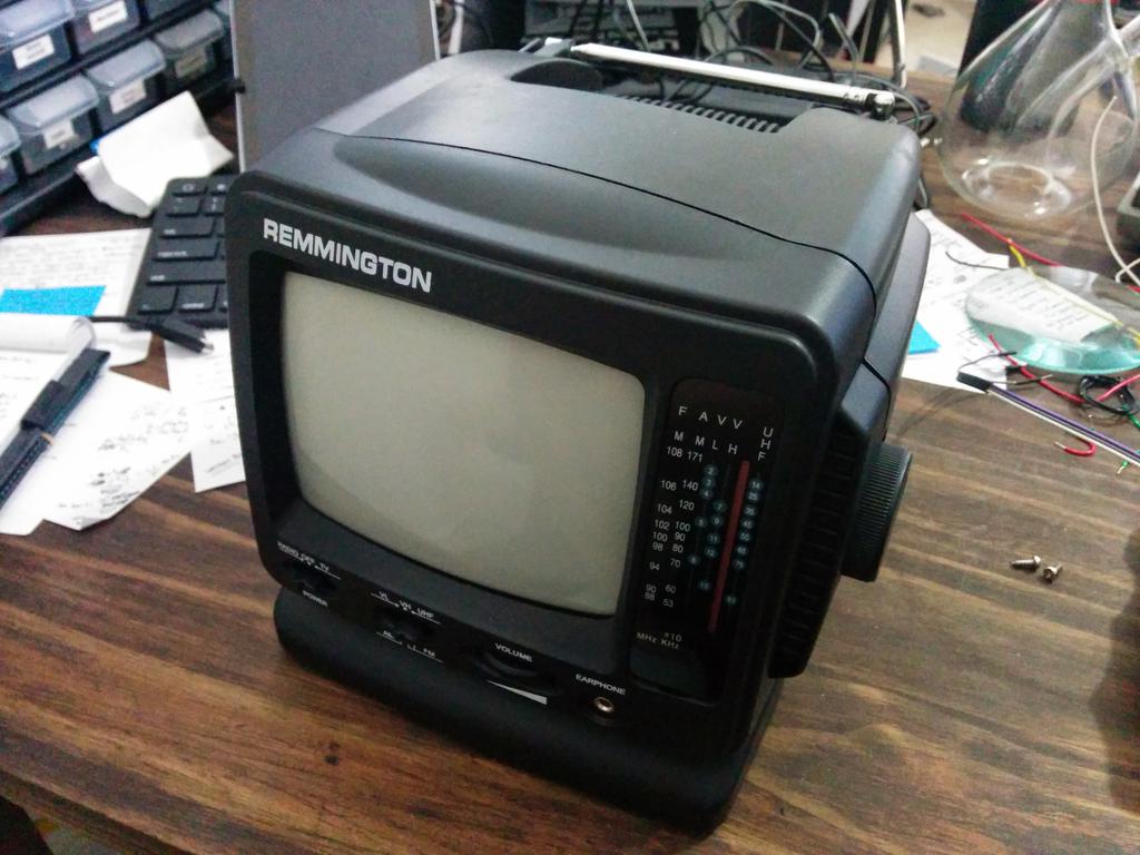
I picked up this tiny 5-AA powered CRT TV (in its original unopened box) at a garage sale for $5, and thought it might make for a great little display for some project. After taking it home, I realized that it only had an input for an external antenna (no composite input), so I figured I'd take it apart and see what could be done about that. Having turned it on before realizing this, I knew I'd need a way to safely discharge the capacitors to handle this thing safely. Battery-powered or not, it's still got a flyback transformer, and could deliver quite a wallop to the unsuspecting handler.
On to the probe!
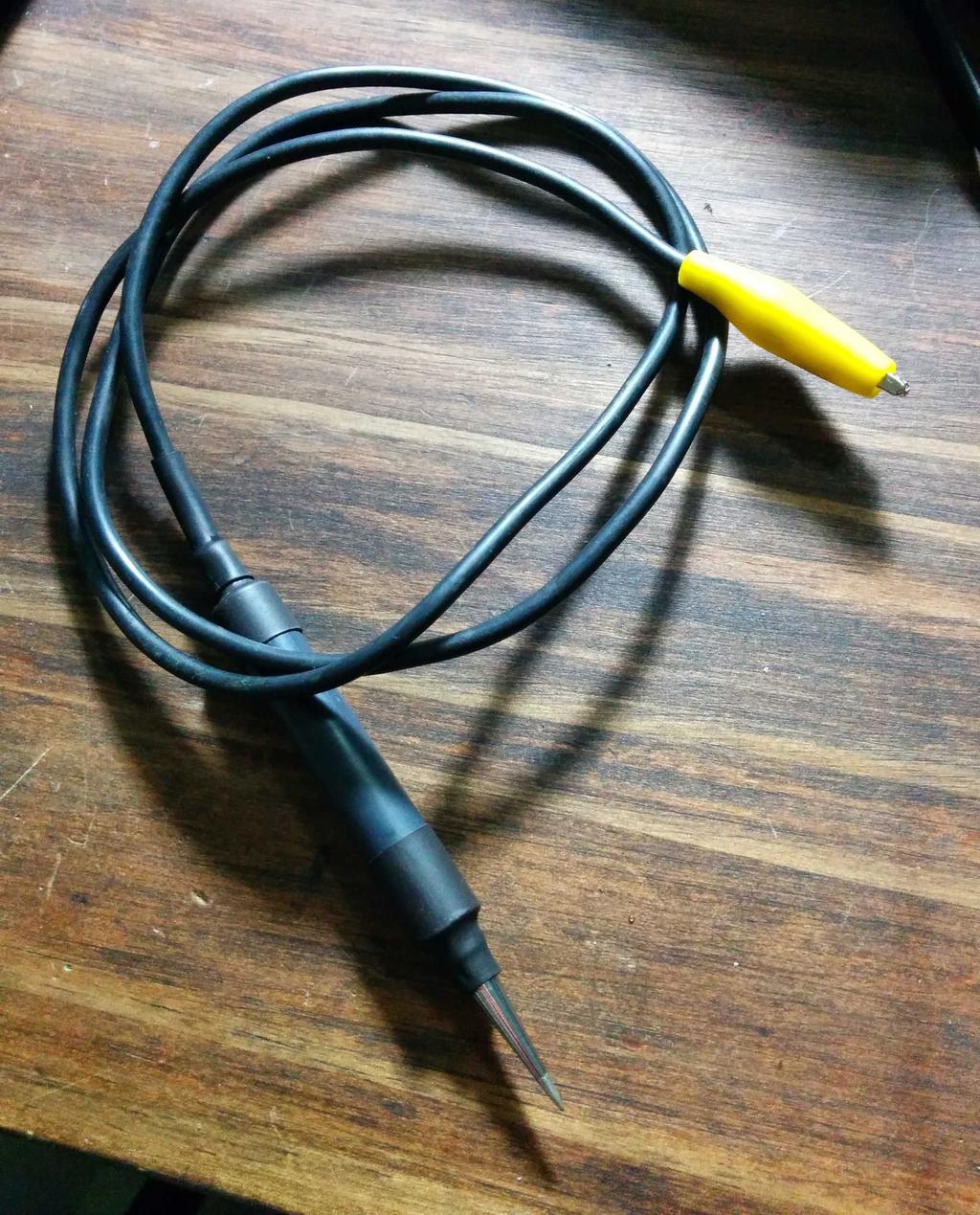
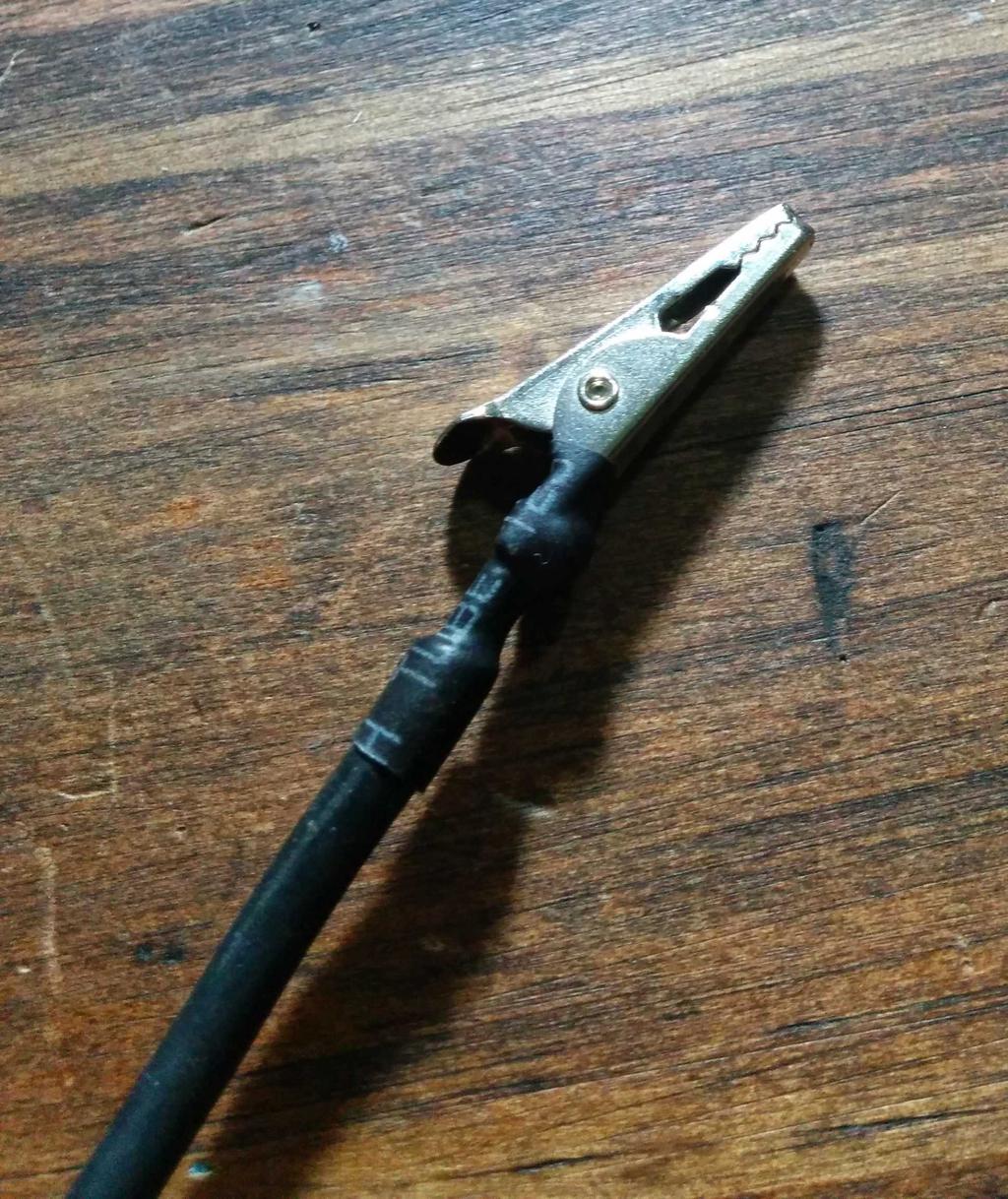
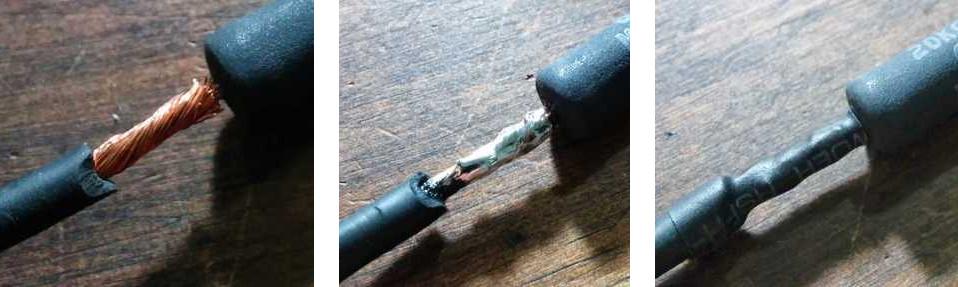
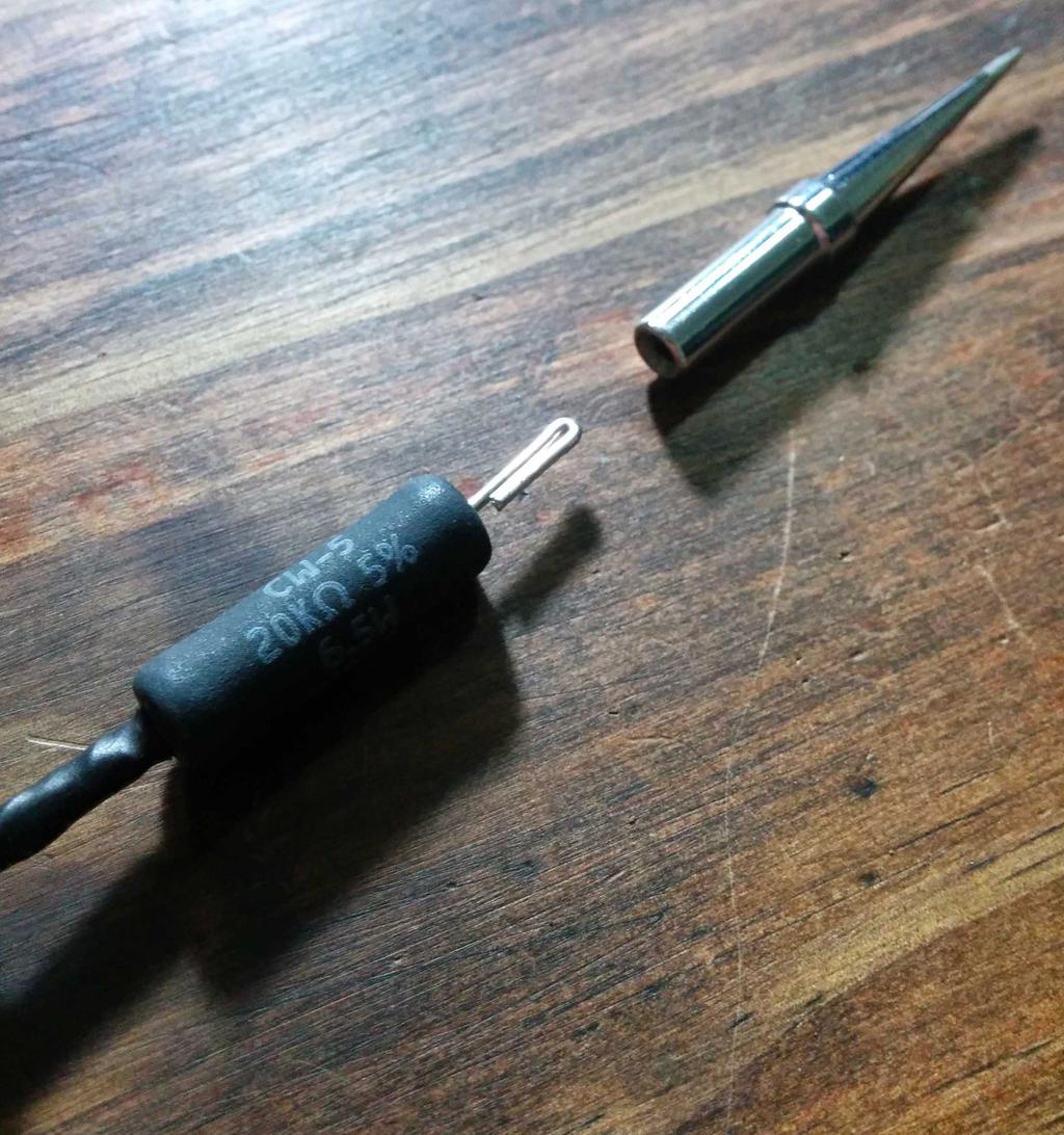
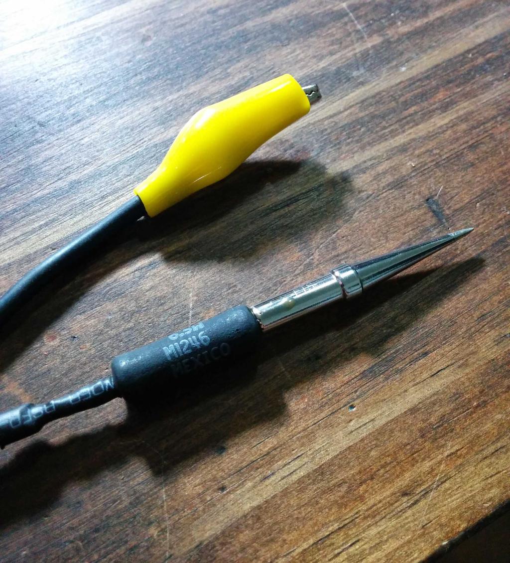
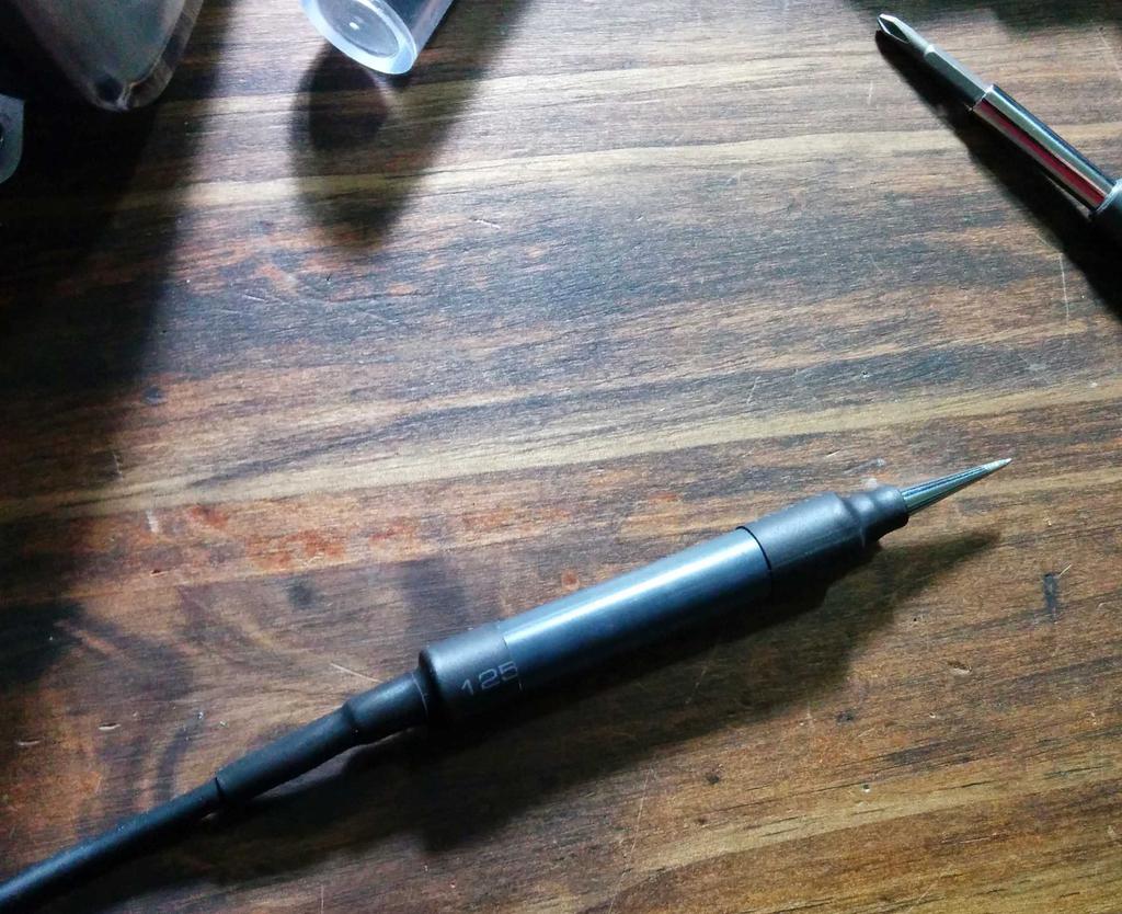
I built this discharge probe from a 6.5 W 20 KΩ power resistor, soldered to a spare soldering iron tip on one end and some thick silicone wire and alligator clip to ground on the other. After heat shrinking over the soldered connections, I slipped a thick plastic tube (recycled from a roll of doggie doo bags
) other them and the resistor, and heat-shrunk that into place, so that it could serve as both a handle for the probe and as an additional isolation barrier.
And what about the TV?
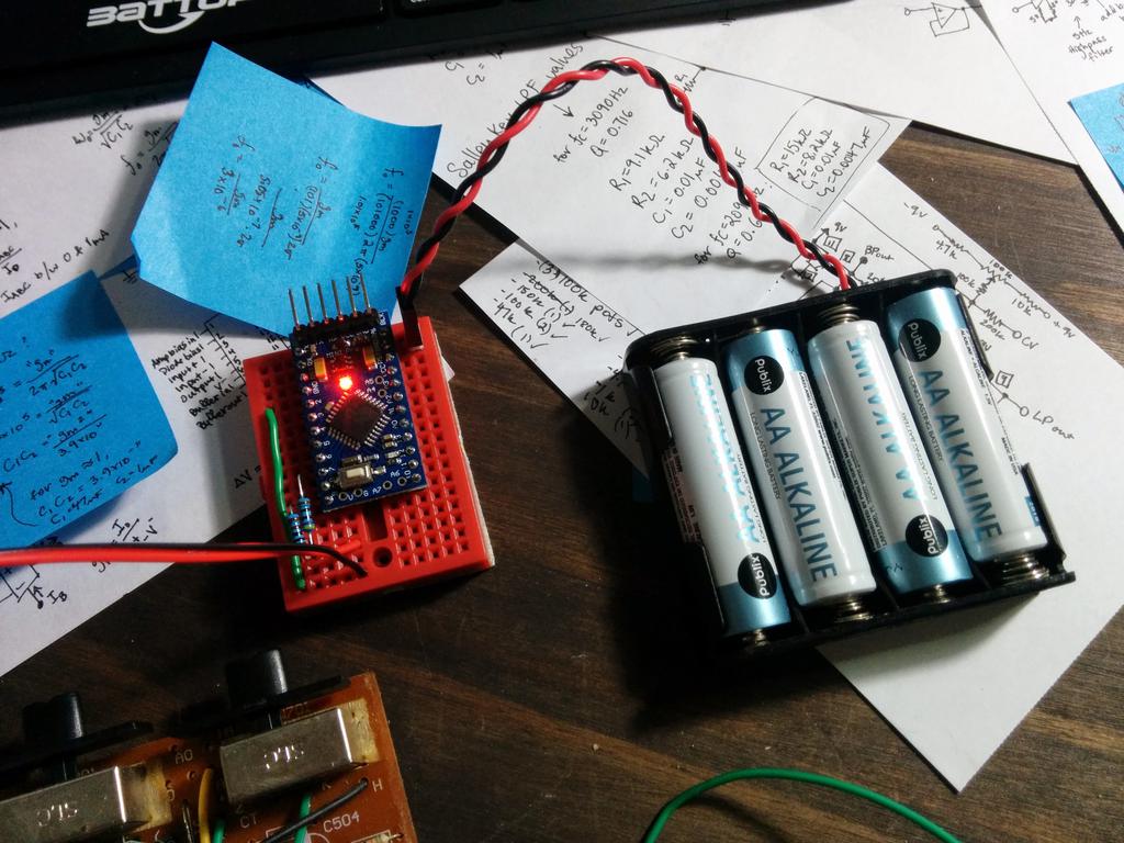
Considering that everything on the TV's PCB was through-hole, and that there was really only one IC on the board (labeled CD5151CP), this was actually pretty easy to get working.
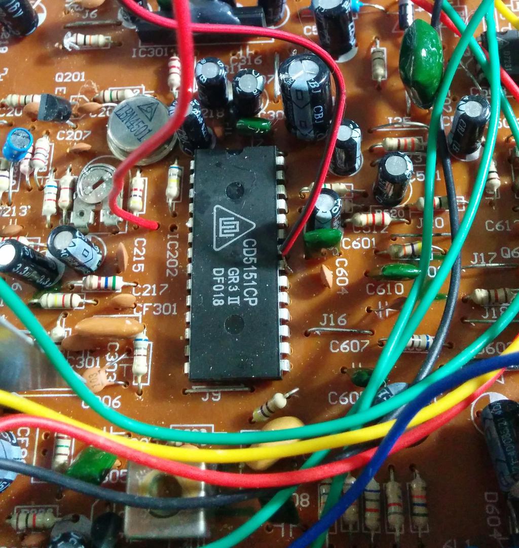
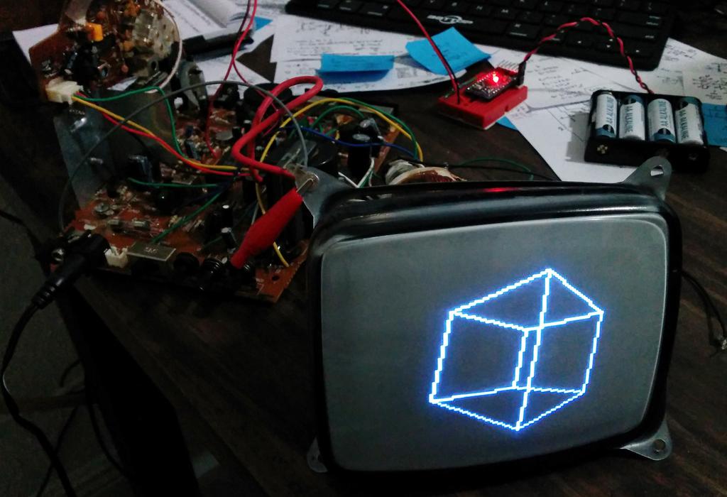
After a quick web search, I came across a Chinese datasheet for said chip; with the help of Google translate, I found that pin 5 was video out (1.8 V - 2.6 V typical) and that pin 21 was ground. From there, I clipped pin 5 from the IC, tapped into the PCB at that point (along with pin 21 for ground), and, pretending it was a composite input, hooked that up to an arduino mini clone running the arduino-tvout sketch with the recommended test-circuit.
Lo' and behold, it worked!
To leave a comment below, sign in using Github.