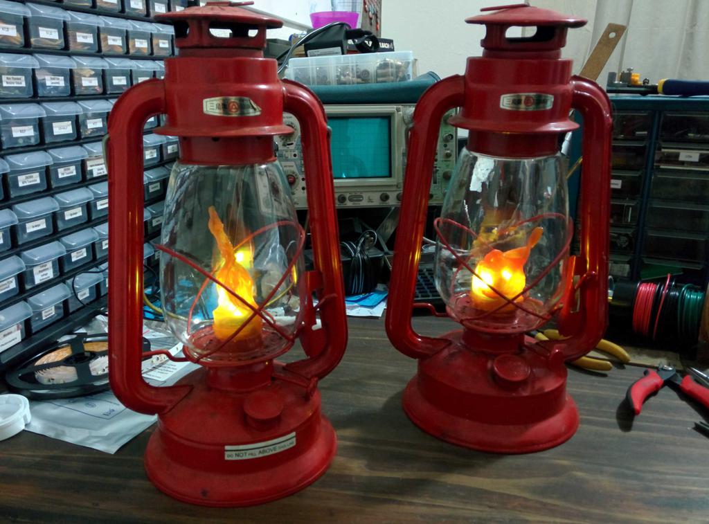
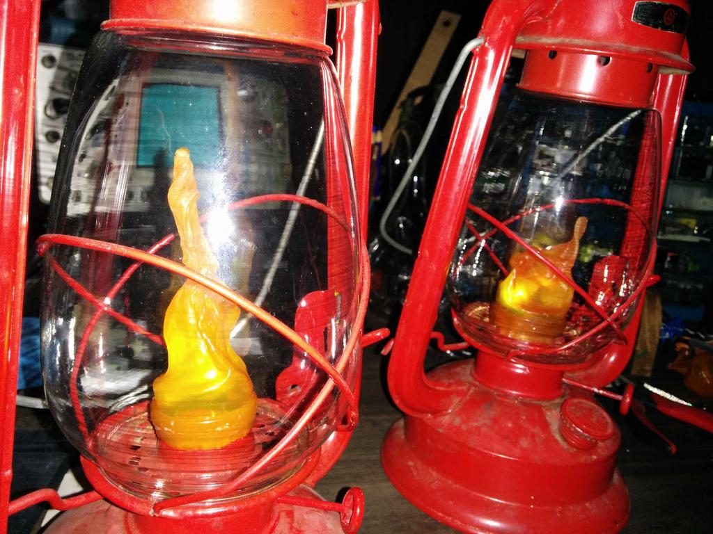
I bought a pair of kerosene lanterns at a garage sale to gift to my younger sister, but wanted to modernize them a bit and make them safer to use. In doing so, I didn't want to change their appearance too much, irreversibly modify them, or significantly change the the way they are interacted with. I'm really happy with how they turned out (my sister loved them too!). Here's how I got there.
First question: if I place an LED in the globe and a power source in the base, how will I turn them on and off without adding a button or switch?
Mechanism
After playing with them for a while, I decided to take advantage of the existing action of the mechanical lift lever, which raises the glass globe from the base of the lantern to expose the wick so that it can be lit. My first thought was to use it to connect and disconnect a pair of exposed contacts, but wire routing would be tricky, and the risk of shorts would be unnecessarily high given the all-metal chassis. I kept looking, and eventually decided to the use the movement to close a normally-open momentary pushbutton hidden between the globe and base.
As there seemed to be enough space for this, I moved on to the next question: what am I going to light, and how am I going to power it?
Power source
I decided to tackle power first. I didn't want to use a rechargeable battery, as that would require my sister to keep track of a charger (or at least a cable) in order to charge it. There also wasn't enough space for one; though the base is large, placing anything larger than a AA inside of it would require significant modifications, due to the existing interior supports. In terms of size, a AA, AAA, or button-cell seemed to be the most practical of the remaining options, of which a AA seemed like the best option.
And what about the light?
Light source
Comparing the 3 mm & 5 mm through-hole LEDs and SMD LEDs from my parts bin (in terms of light output, beam angle, and current draw), I settled on a short length of 12 V 3258 SMD LED strip (3 LEDs-long). To power this, I would need to boost the 1.2-1.6 V range of the AA to the 12 V needed by the LEDs. A Digikey search for boost converter ICs matching these specifications did yield a few results, but each would also need a few discrete components (including an inductor) to yield a working circuit. If I would need an inductor anyway, I decided to skip out on buying a boost IC and build a 'joule thief' instead, which would require only a mutual inductor, a transistor, and a resistor. This would also allow nearly all of the capacity of the AA to be utilized, and provide a use for all those dead
TV remote batteries.
Circuit
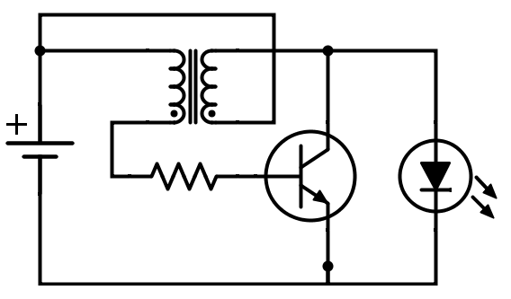
A joule thief is a self-oscillating voltage boost circuit that may be driven by a very low input voltage, which can produce an output voltage many times greater than the input, depending on the transistor and inductor used, with switching frequency dependent on inductance. Joule thiefs are pretty flexible when it comes to component values, and though efficiency can be improved through careful component selection, when they work, they work.
I didn't have any matching mutual inductors for the two lanterns, but I did have an identical pair of toroids and magnet wire, so I wound my own.
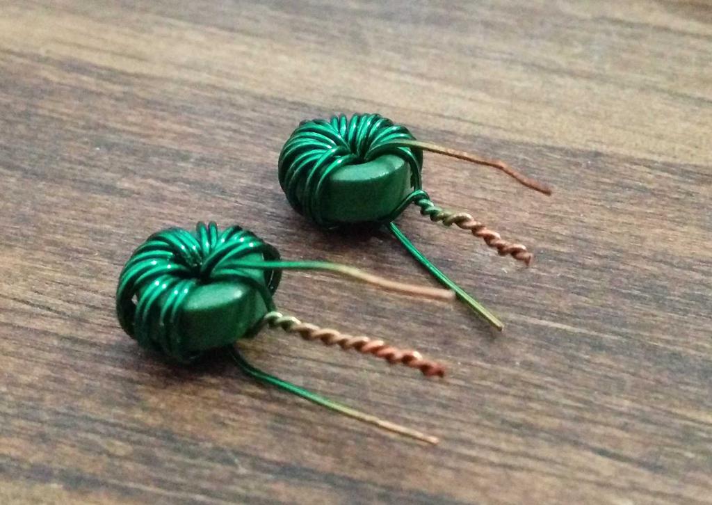
To measure their inductance, I set up a series RLC circuit (consisting of one side of the inductor, a 102.4 nF ceramic capacitor, and a 1 k resistor), with constant-amplitude sine wave input from a function generator, by measuring the voltage across the resistor while manually sweeping the frequency of the sine wave. The frequency at which the amplitude is greatest is the resonant frequency of the circuit, related to the inductance by L = 1/[(2πƒ)²C]. The resonant frequency (of both inductors) was measured to be about 98.0 kHz, and the inductance (one side of the mutual inductor) was calculated to be about 25.7 uH.
These inductors, along with PN2222 NPN transistors, 1 k resistors, and pushbutton microswitches (between the battery and toroid) were used to build the joule thiefs. Testing the circuit on protoboard with a spent AA from a TV remote yielded good results.
After protecting the circuit with heat-shrink and electrical tape, I hot-glued it in place under the glass globe, so that the microswitch would be pressed when the globe was lowered to the base using the lift lever, and slid the battery into the base. This functioned nicely, but the lantern still didn't quite look like a lantern without a flame.
One of the LEDs that I tested earlier was flame-shaped, similar to what you might find in a battery-powered tea candle.
I considered using this at the beginning, but after putting it next to the lantern, it seemed a bit too cheesy — too small, too dim, too fake. Having already decided against these, I still needed something to diffuse the blindingly bright LEDs, and ideally, something that looked like a flame. Walking around the house, I stumbled upon a bit of inspiration: an empty orange pill bottle. Could I make it look like a flame? Let's see.
Flame
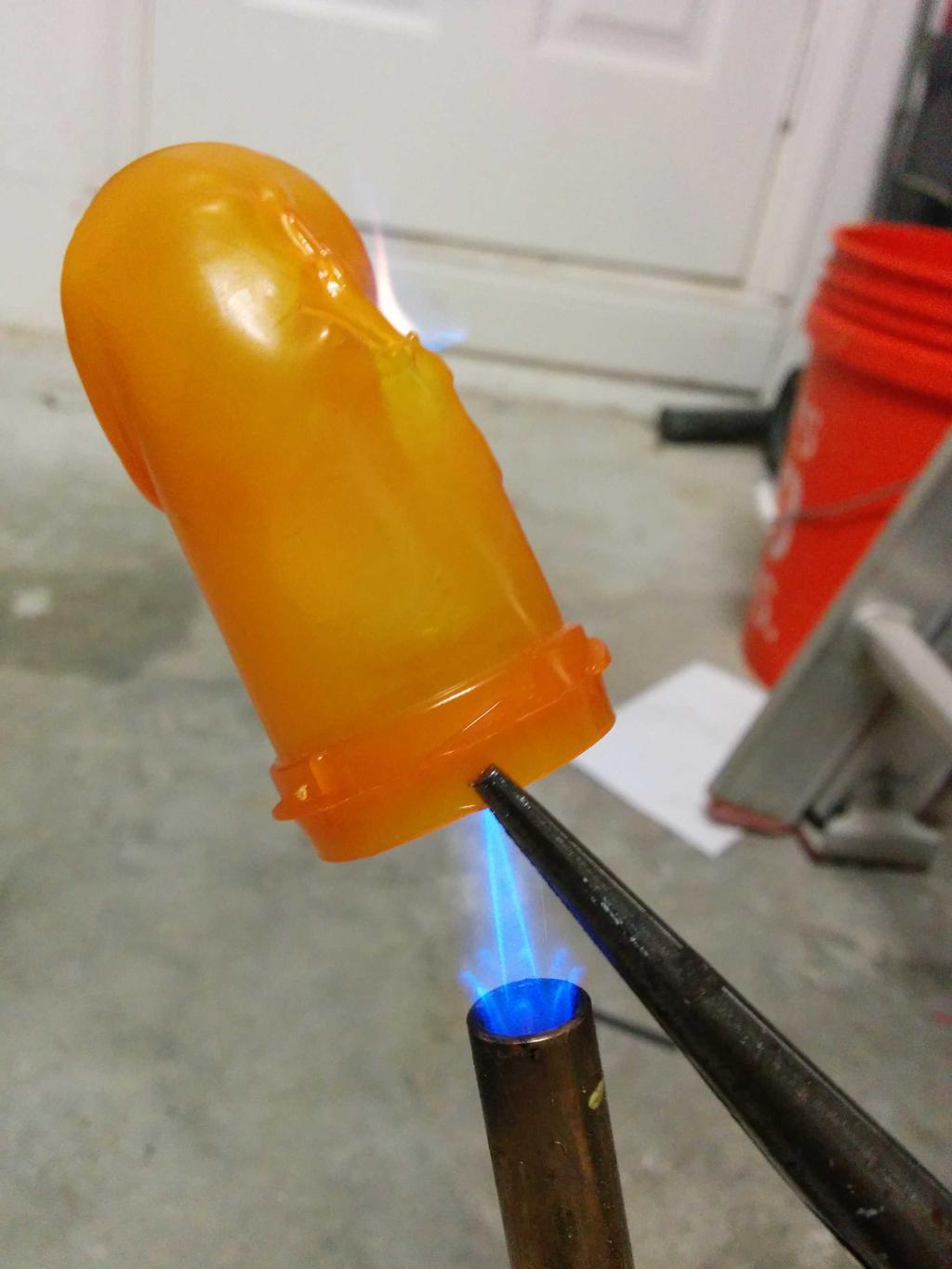
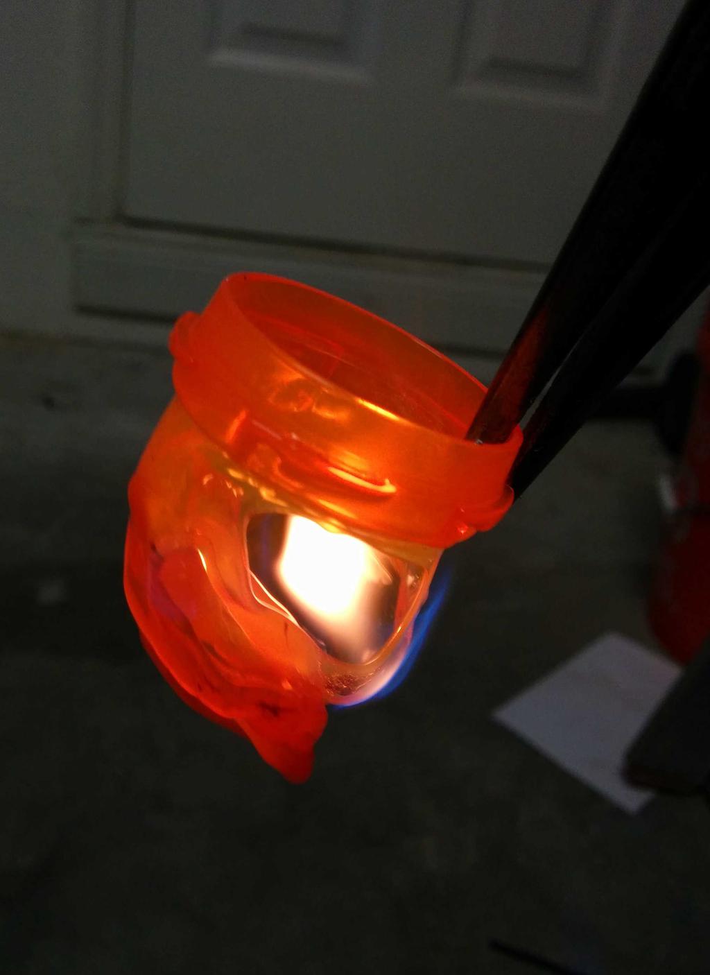
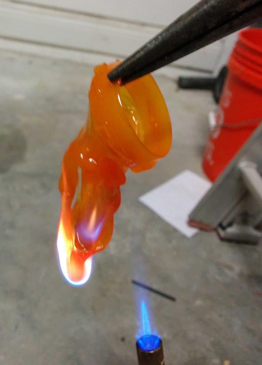
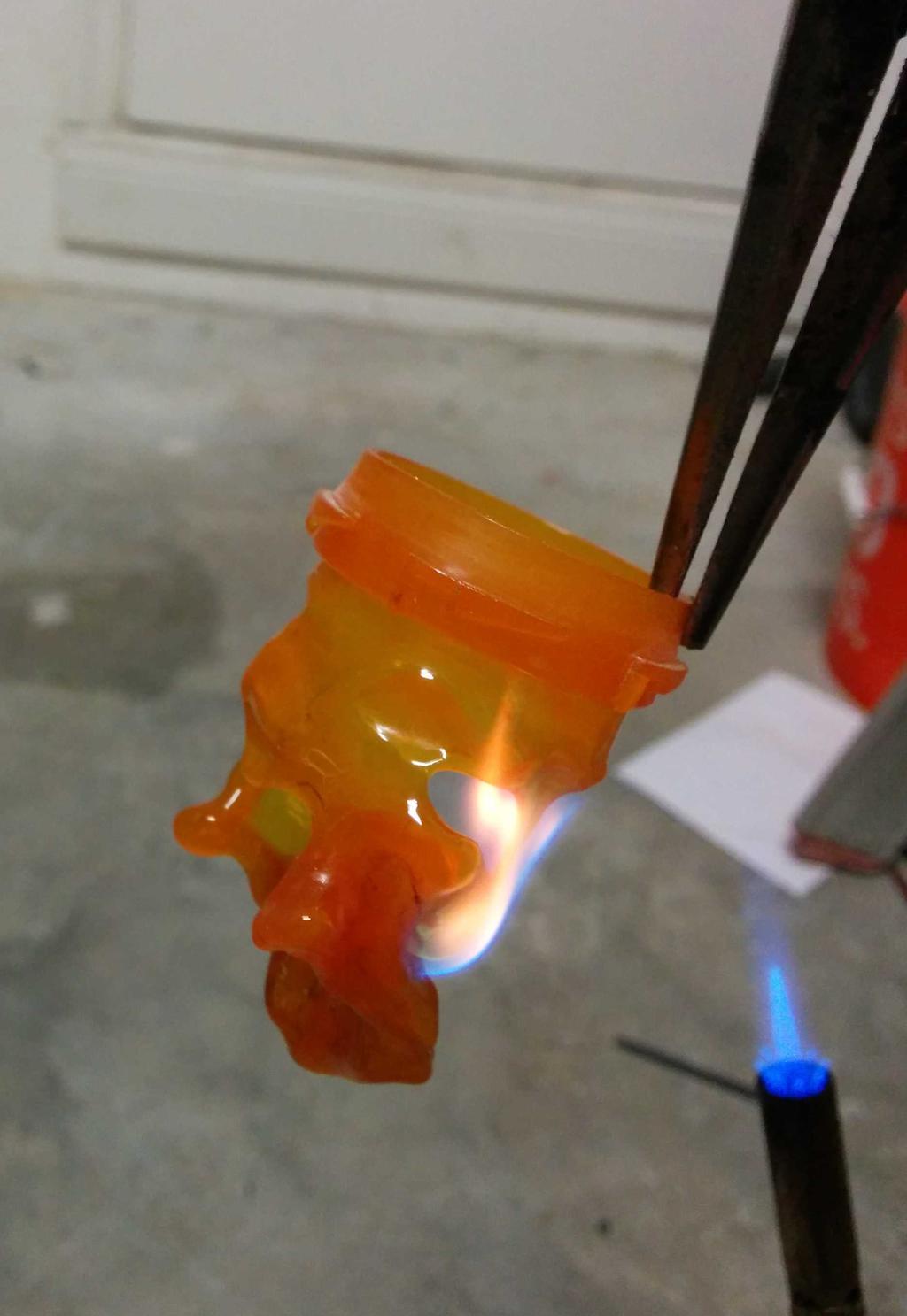
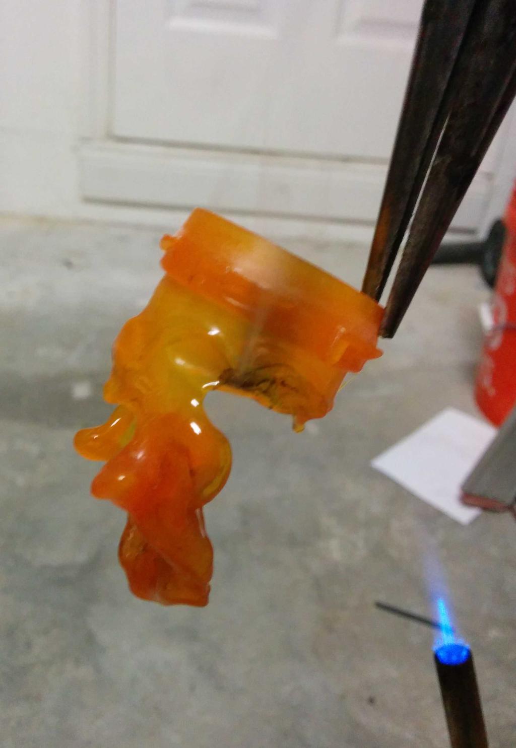
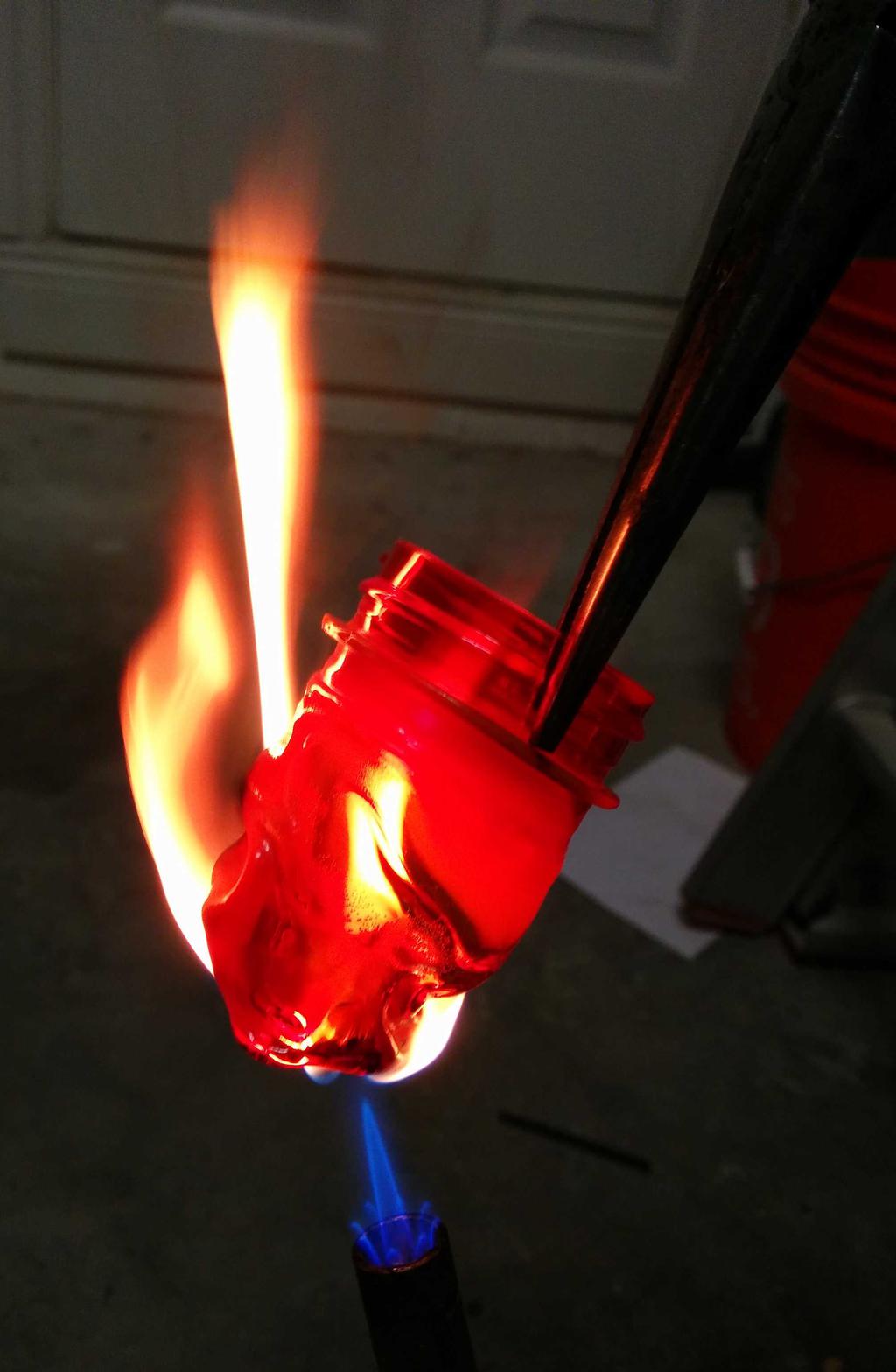
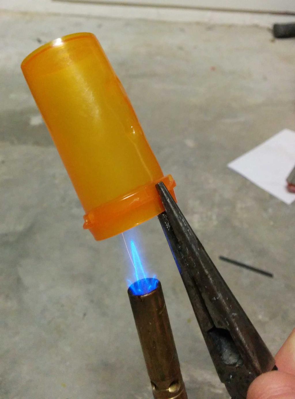
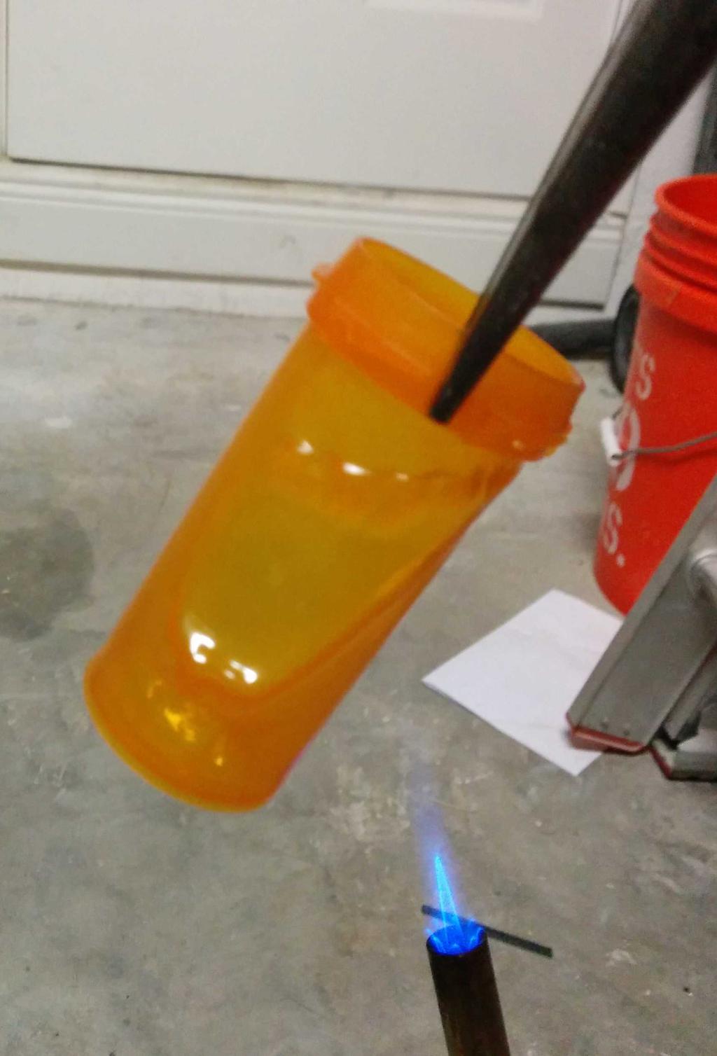
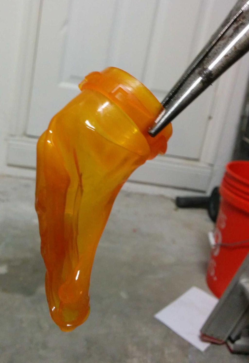
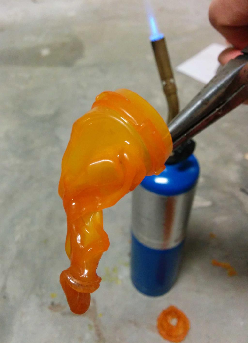
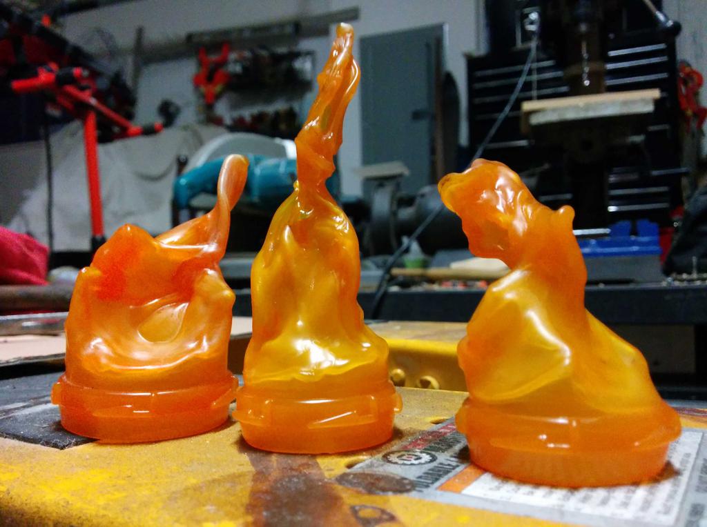
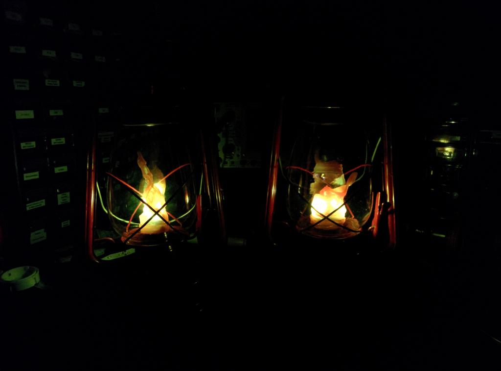
With 3 plastic flames to choose from, I was in good shape. After picking my 2 favorites, I cut the lid-locking ridges from the base of the flames, and glued them into the glass bulb with hot glue. All together now!
To leave a comment below, sign in using Github.