Background
In setting up an electro-olfactography rig at work (using the commercial alternative to my uEOG, currently in development), I faced a noise floor higher than the signal I sought to record, consisting almost entirely of 60 Hz mains hum. After attempting to minimize this noise (e.g. by turning off the fluorescent lights, shielding the recording field with aluminum foil, grounding nearby metal) and determining that these alone would not be satisfactory, I decided to build a small Faraday cage. Here's what I built after a short trip to Home Depot, $25, and a few hours of work.
A Faraday cage blocks external electromagnetic radiation (like the aforementioned 60 Hz noise, often a problem when amplifying small signals) of frequency significantly higher than the diameter of holes in the walls of the cage. To attenuate 60 Hz hum, pretty much any fine mesh will do (a 60 Hz wave has wavelength λ = c/ƒ = (3x10⁸ m/s)/(60 Hz) = 5x10⁶ m) as long as it is thick enough and is sufficiently conductive.
Putting it together
A stroll through Home Depot revealed two main options: galvanized steel chicken wire of various mesh sizes (1/4and 1/2
), and aluminum insect screening with rectangular holes of around 1.5 mm x 2 mm, both available for less than $10 for a 4' x 8' roll. Of these two, I chose the aluminum mesh, though either should have worked here. To seal the seams of the cage, I used aluminum foil tape, and for grounding, 16 ga stranded copper wire. The edges of the box (the only pieces of which I didn't buy at Home Depot) were made from 5" wooden cotton swabs (stripped of the cotton); bamboo skewers, among many alternatives, could have also worked here.
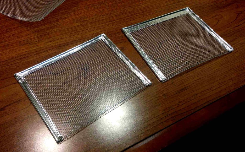
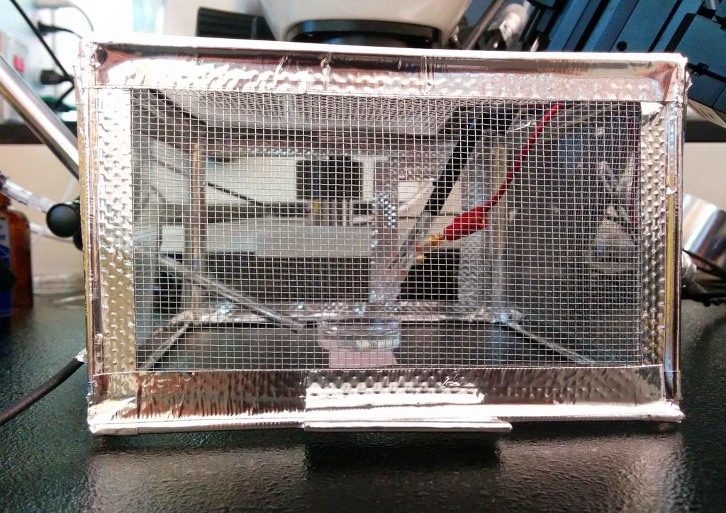
To start, I decided to make a (roughly) 3.5tall box with a 5
square footprint and hinged front-door. First, I cut the tape into strips, and wrapped them around the wooden sticks, which were cut into 5and 3.5
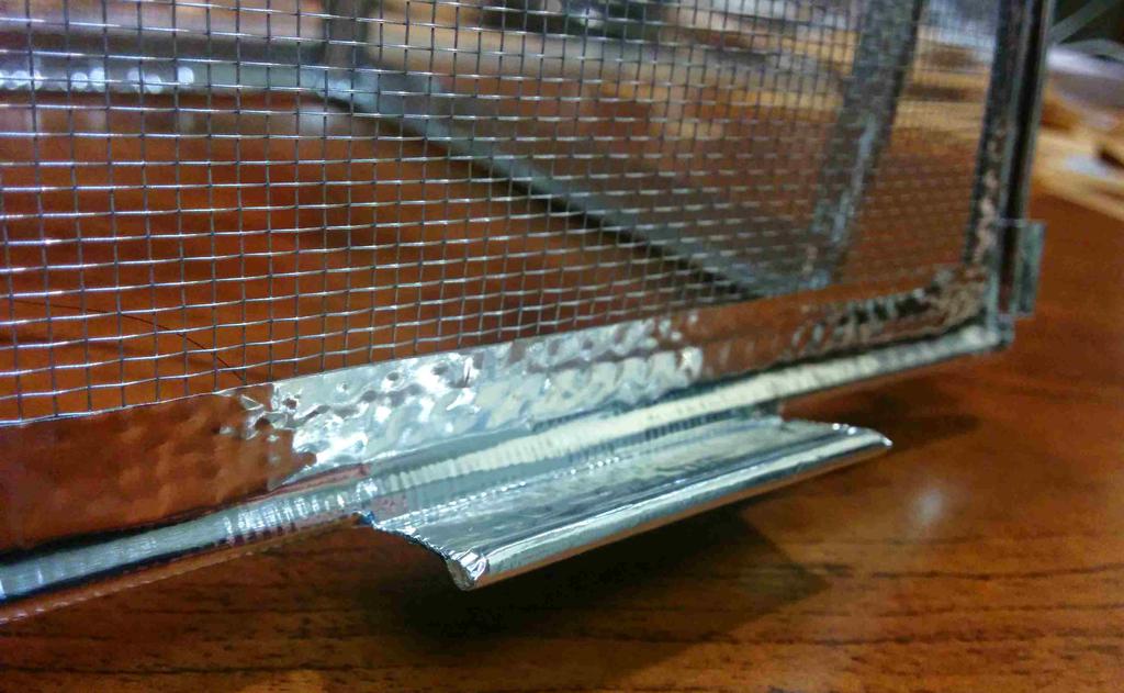
lengths. I did this to make them conductive; once the mesh is taped around this, all sides will be continuously connected. Edges of the cage were connected using small squares of the tape, wrapped around the ends of the sticks with about a 1/4gap between them, so that they could be bent at 90 degree angles. Because the adhesive of the tape might provide enough separation between the tape and mesh to be electrically insulating, the mesh for each side is over-sized so that it directly contacts the aluminum wrapped around each stick. For two of the sides, three sticks (3.5
, 5, and 3.5
) are connected in the same way, and taped to three sides of an over-sized rectangular section of mesh. These were then connected to the square frame made for the top, and mesh was taped to the top and back of the frame.
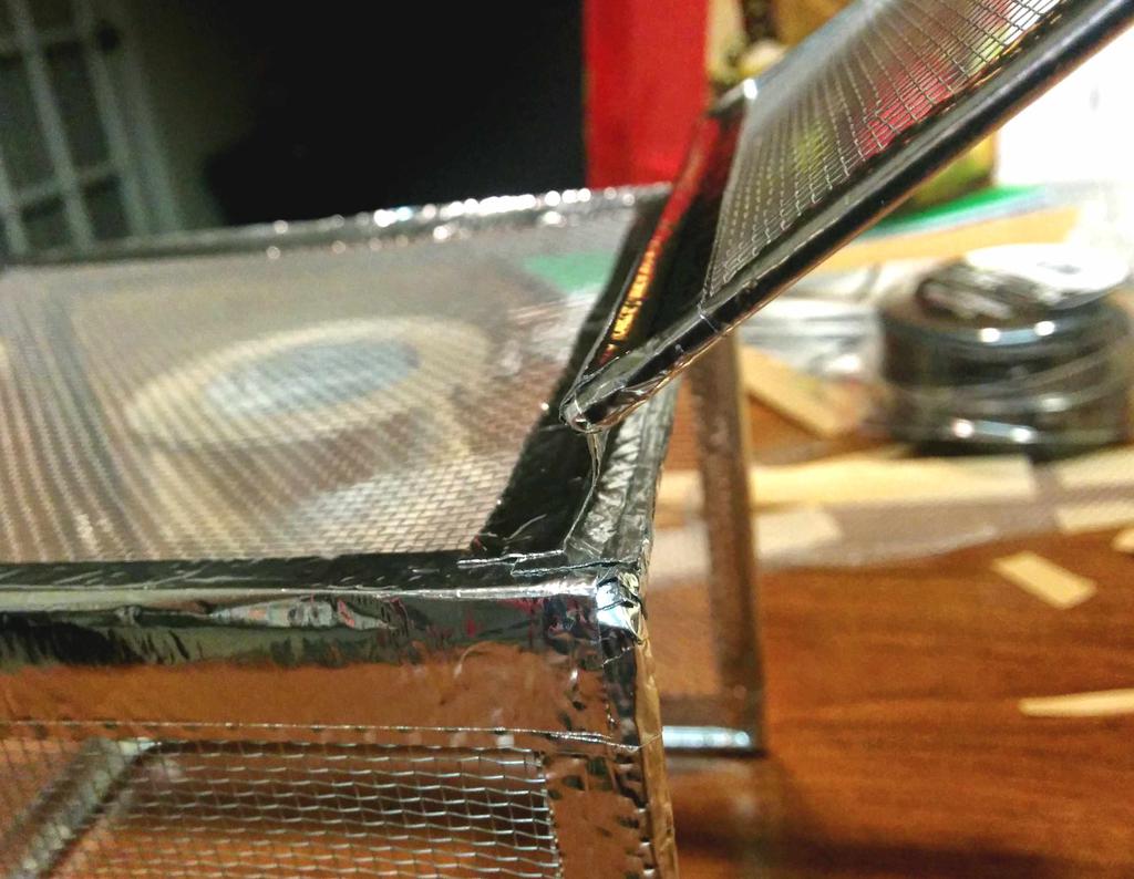
A small door was made for the front of the box in the same way, with a four-sided frame and a piece of mesh. This is in hinged to the box using a strip of tape, and a small handle is made with a piece of rod and more tape.
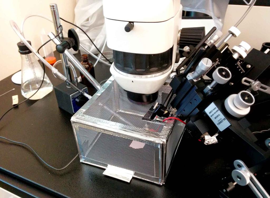
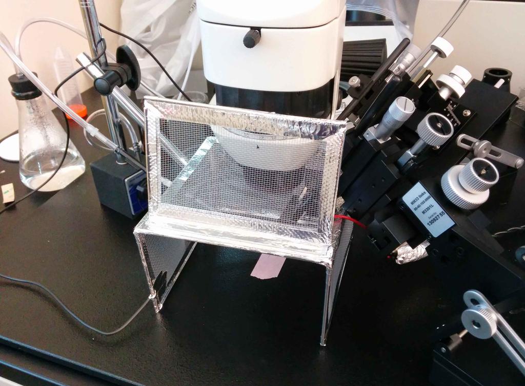
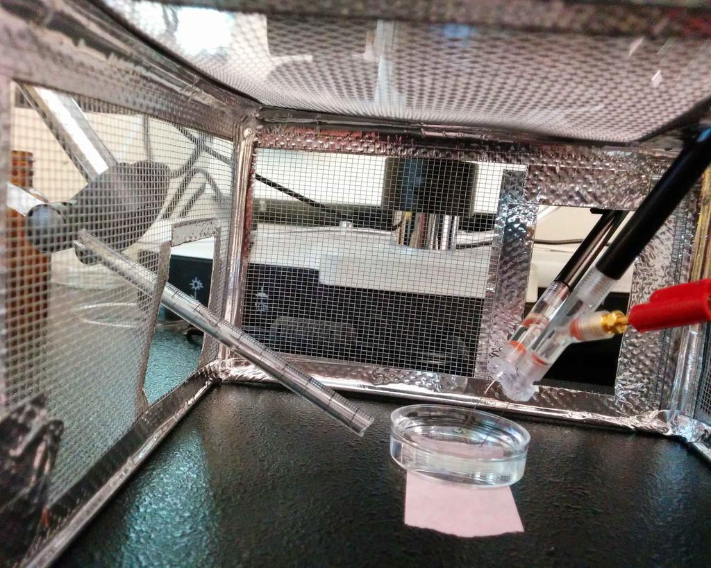
After taking this to work, I fit it under the dissection scope where it would rest, cut about an inch from the height, and cut access holes in the sides for the reference and signal electrodes, and for the air/odorant stream.
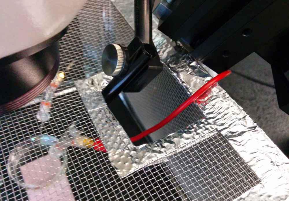
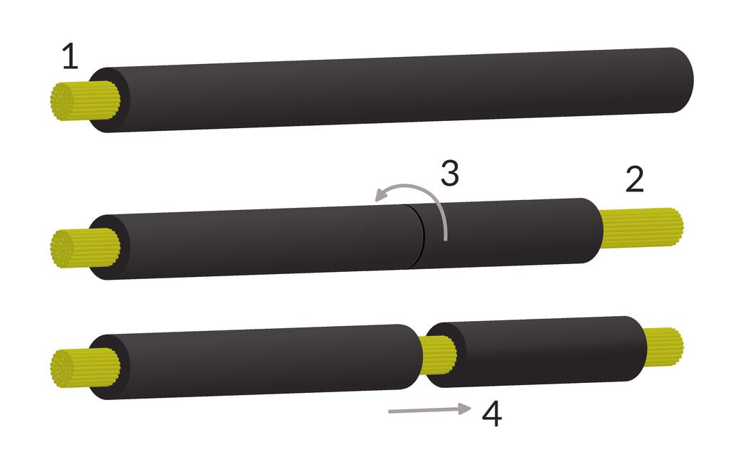
After fitting the cage to the recording area, I grounded the cage to (a bare spot of) the metal plate on which it sits, and this plate to the metal bench. After stripping several sections of a single segment of wire (see image below), I connected various floating portions of the setup (the boom of the dissecting scope, the micro-manipulator electrode holders, and the magnetic stand holding the air tube) to the same ground point.
Assessment
Using bare wires as electrodes (placed in a dish of Ringer's solution) I took a baseline recording, which I compared to a similar recording taken before installing the Faraday cage (with similar grounding). Beautiful! Installation of the Faraday cage immediately resulted in a 40 dB attenuation of the mains hum (100-fold decrease in amplitude), bringing it well-below the signal amplitude. And after narrowing down the source of some of the remaining hum to a particularly noisy power brick, and by adding some additional shielding, I was able to attenuate it by an additional >20 dB. With these tweaks in place, the noise now amounts to between 5 and 10 uV peak-peak at the recording site. Awesome!
Looking for further reduction of mains hum? Try a mesh with thicker conductors!
To leave a comment below, sign in using Github.