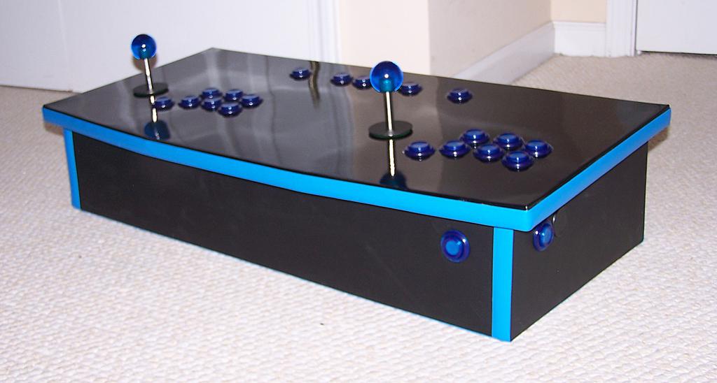
I completed this arcade control panel, the Token Taker,
in 2008. I've never been much of a gamer, but thought it would be a fun little challenge. Hidden inside was an old desktop computer, which I configured to create a plug-and-play experience with any TV compatible with composite or S-video input. I originally posted this build log to another site in 2008, and have copied it below, more or less verbatim, for posterity.
Ideation
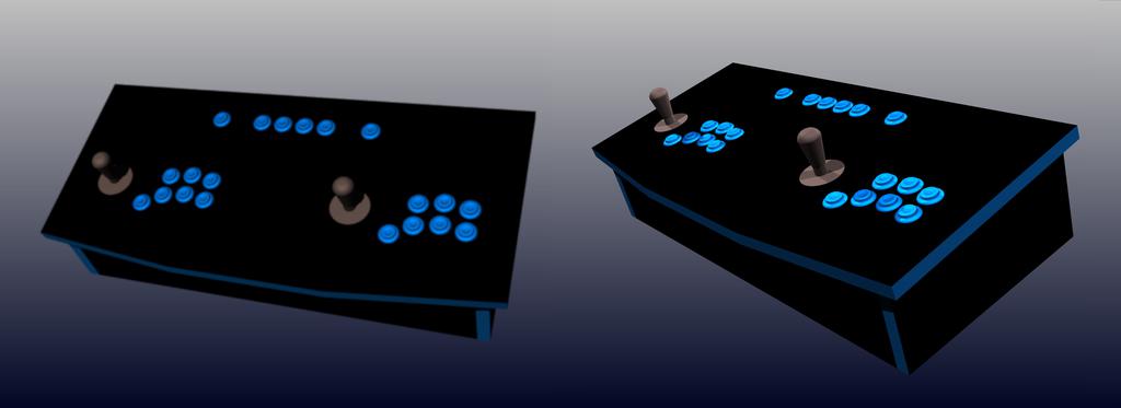
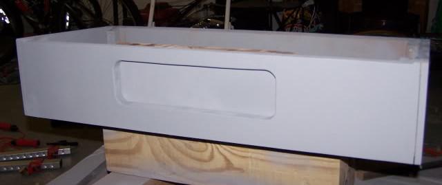
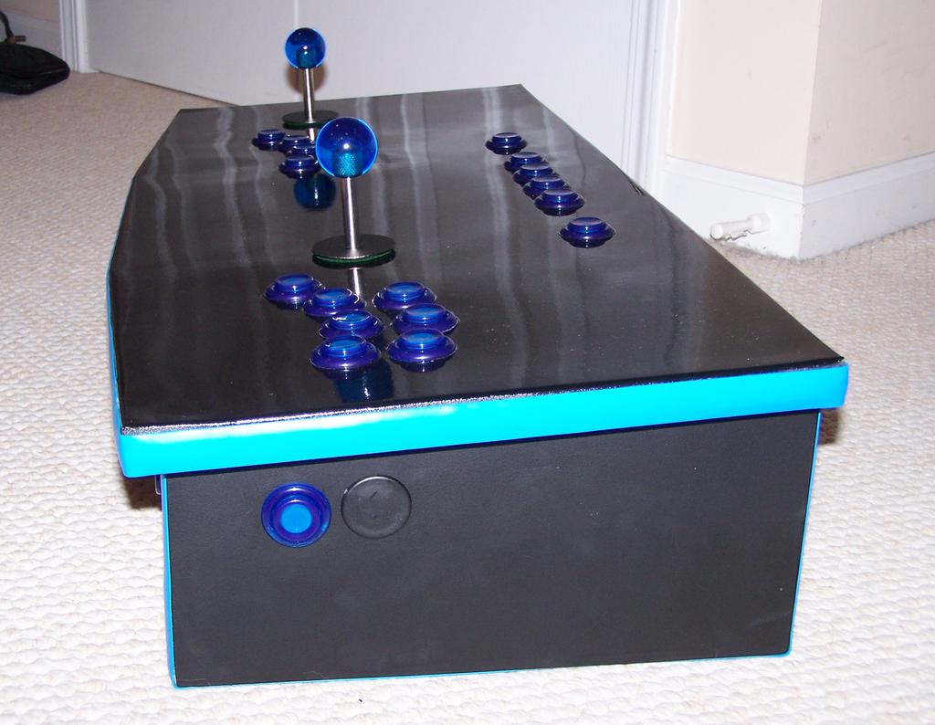
I decided to make it solid black with light blue t-molding, have no exposed fasteners, and have a thin galvanized steel top (resting atop 3/4MDF). The top will be painted with a heavy-duty high-gloss enamel paint (Plasti-kote Industrial Spray Enamel), and the rest will be painted flat black. It will have two joysticks, each sitting next to seven light-blue pushbuttons, and will have 6 other pushbuttons (player 1 & 2, coin insert 1 & 2, pause, and escape). The computer will be interfaced to the controls using a GP-Wiz Eco, a keyboard encoder board, and the cost will be kept low by keeping it simple, and by using as much of what I already have as possible. The top panel will be 30
wide and 14deep, and the box below the panel will be 6
tall in the back, and 5" tall in the front.
Construction
Enclosure
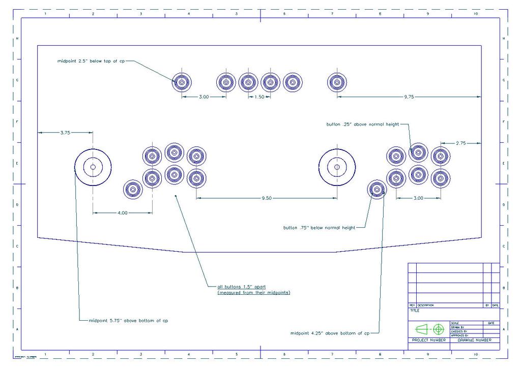
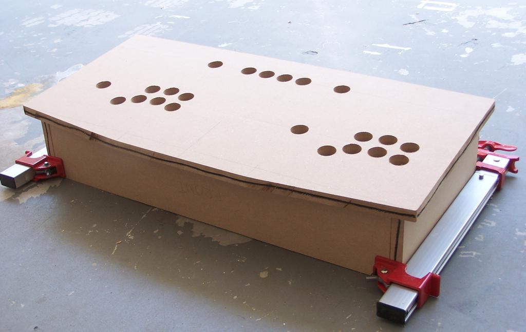
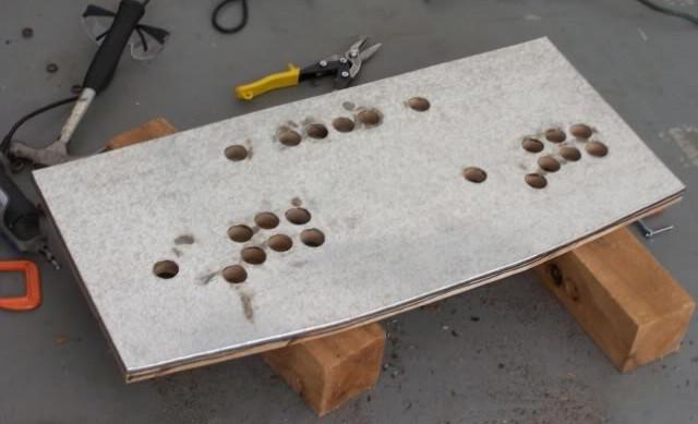
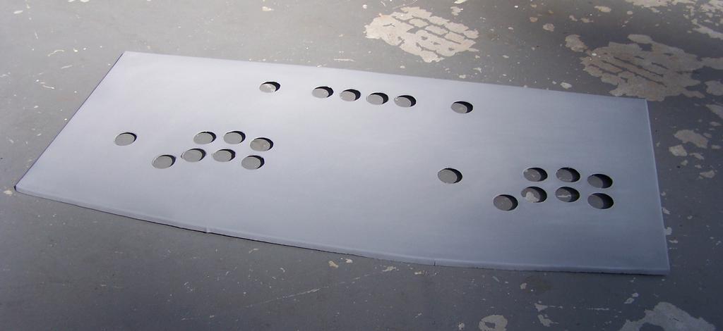
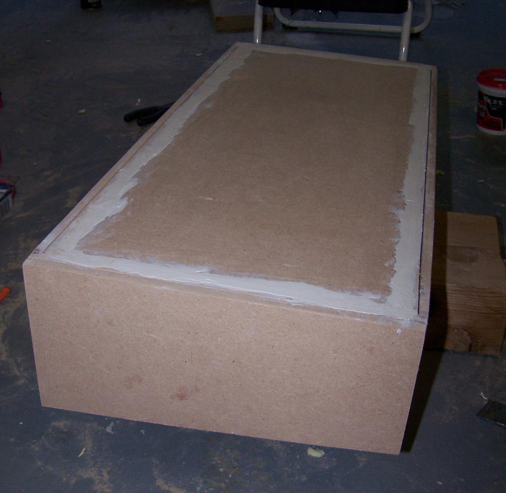
Having already mapped my control layout and hole placement in PTC Pro/Desktop, I cut the body panels from MDF, and drilled the holes.
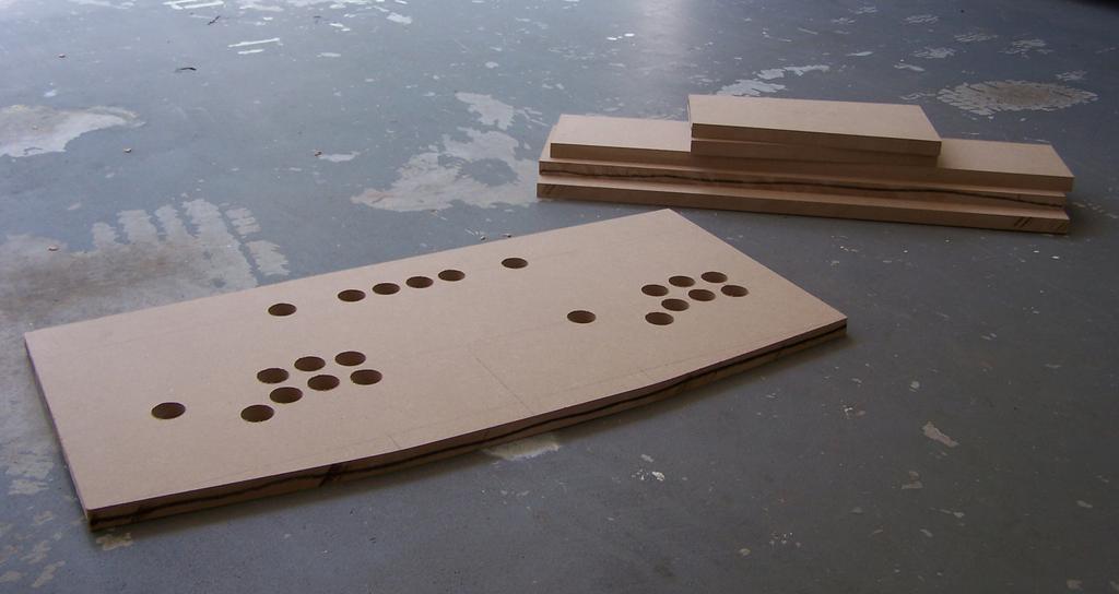
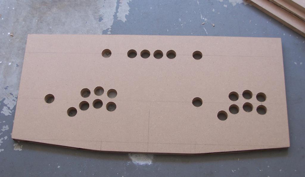
After cutting the pieces, but before fastening them together, I set them up for a fit test. Looks good; feels right!
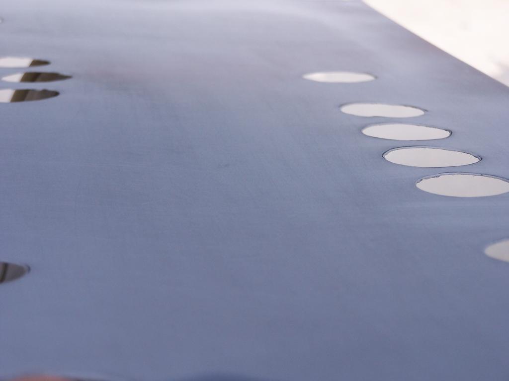
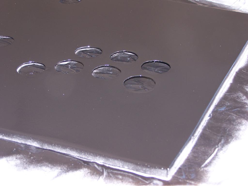
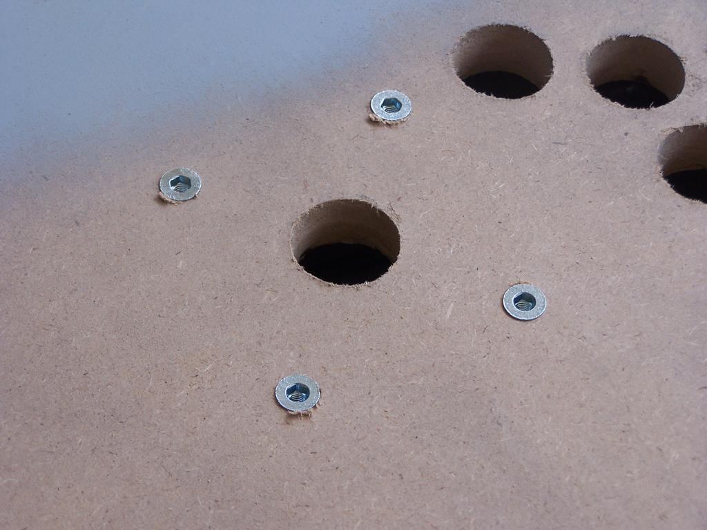
Next, I laid the galvanized steel sheet (26 ga.) atop the MDF, and drilled the holes. Note that the steel sheet was cut 1/4" larger than the MDF in all dimensions, so that the edges could be bent over the edge (but under the t-molding) to hide any sharp edges.
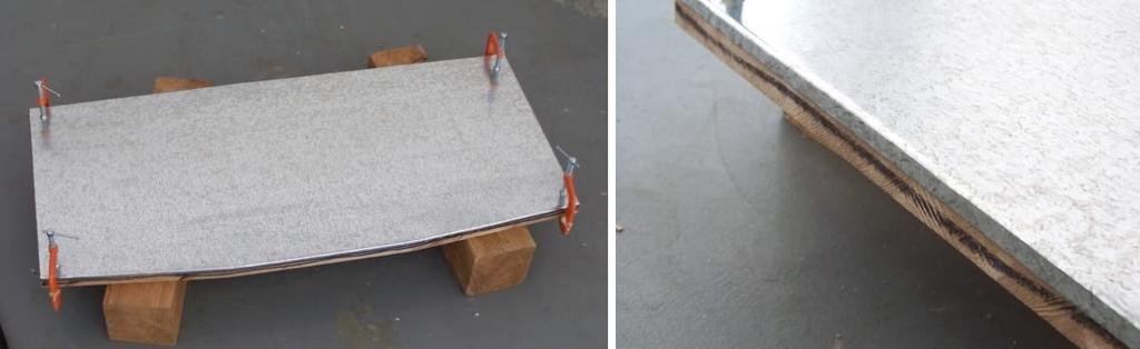
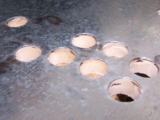
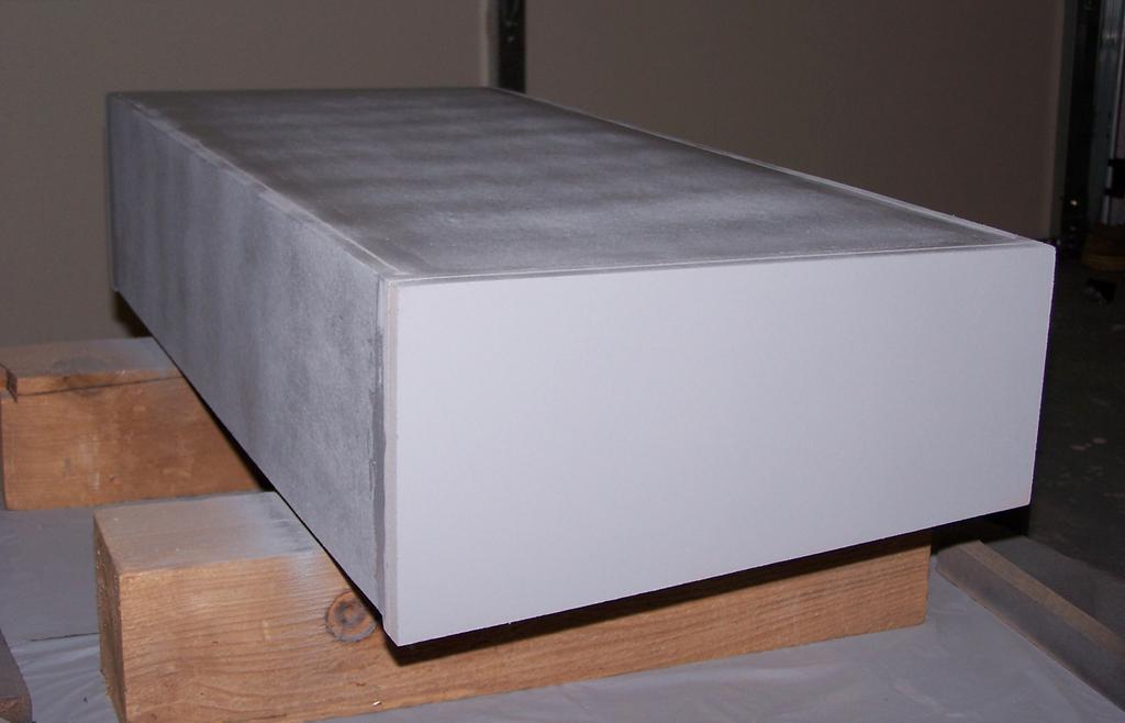
After priming the top, I sanded it smooth, and proceeded to paint. Note from the future: I sanded the paint, not the galvanized steel. If you can avoid it, never sand galvanized steel; if you must, be sure to wear a respirator.
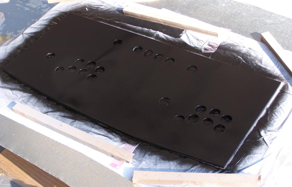
Due to irregularities in the paint (some areas were quite shiny, others were dull and rough), I needed to wet-sand quite a bit between each layer, and after several coats, still couldn't achieve a consistent finish. Working on the hypothesis that vibration of the wet paint might help to smooth out these defects, I made a vibrating table, consisting of a downward facing box-fan (which vibrated quite nicely) and 2x4s on opposite edges of the top and bottom of the fan (to allow airflow). I put a piece of scrap metal on top of this, and placed the galvanized steel top atop that. While painting, I turned on the box-fan, causing the top to vibrate as I painted it. As crazy as this all sounds, it worked!

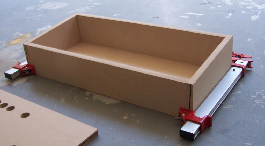
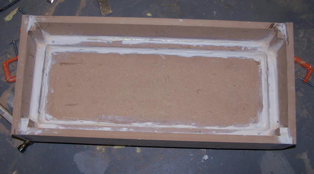
Borrowing a router from a neighbor and using a 1/8" slot-cutter bit, I routed slots into the edges of each panel for the t-molding.
To hold the box together, I screwed 1x 1
strips of wood into each inside edge of the box. I then puttied all of the seams (overzealously, it seems), sanded them flush, and primed the box for paint.
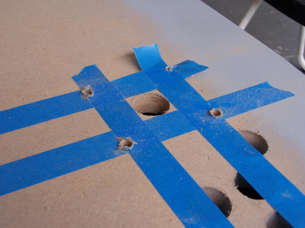
Before continuing with paint, there were a few more details to finalize. On the underside of the control panel MDF, I laid out and drilled mounting-holes for the joysticks.
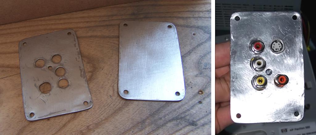
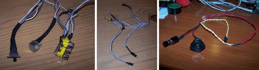
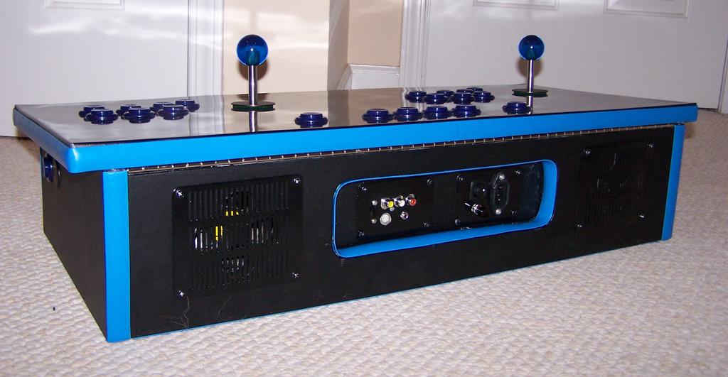
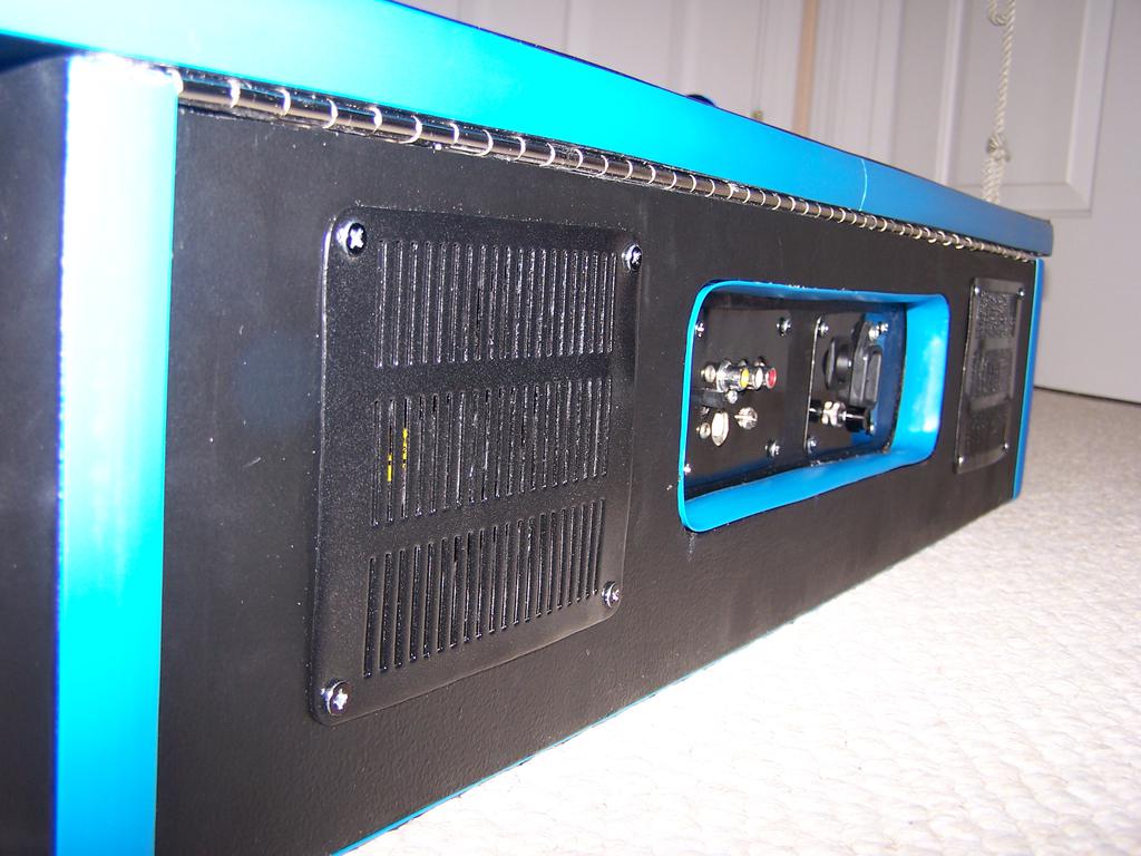
After harvesting A/V connections from an old cable box, I made A/V-out and power-socket mounting panels for the back of the control panel using some of the remaining galvanized steel sheet.
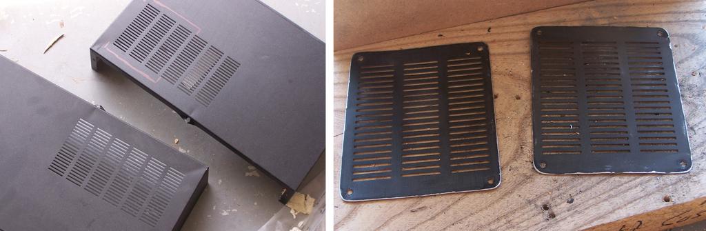
From the enclosure of the same cable box, I harvested vents for use as fan grilles.
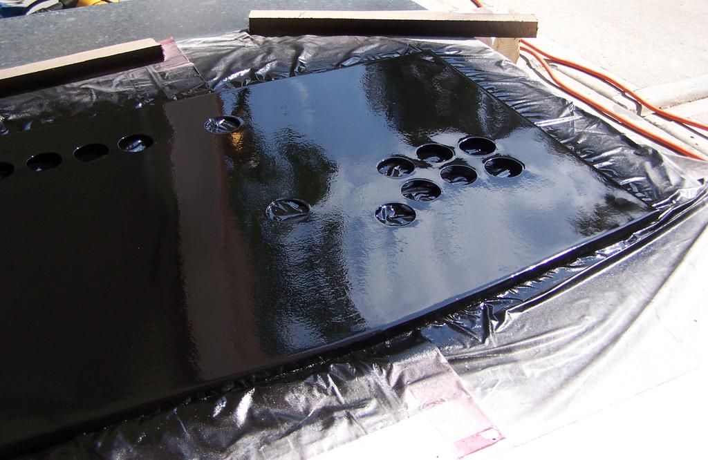
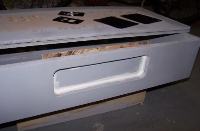
To help protect the connections in the back of the control panel from bumping, I recessed a section of MDF on the back. The fan grilles were eventually placed on both sides of this recessed area. To mount the top of the panel to the body, I used a piano hinge in the back and wooden blocks covered in heavy-duty velcro in the front (inside the box, to hold the top closed).
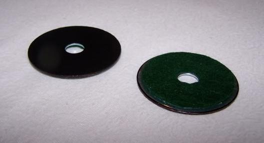
To protect the top of the panel, I cut pieces of self-adhesive felt and attached them to the underside of the joystick dust-washers (surrounding the shafts, covering the large holes that that must be drilled to accommodate their movement).
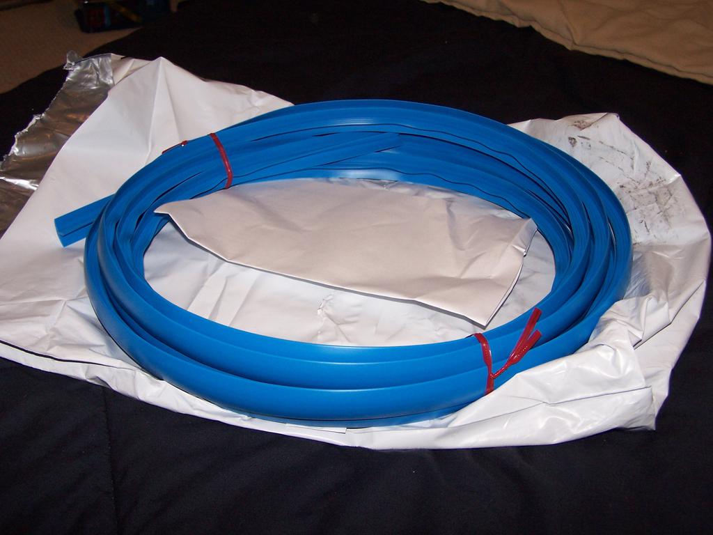
Around this time, I also pressed the t-molding into place.
Electrical
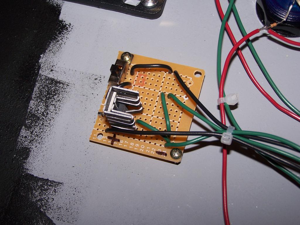
Before mounting the buttons to the panel, I placed labels on the inside of the configuration buttons (to be lit up from beneath with LEDs), and wired the A/V (S-video, S-video-to-RCA adapter, RCA and 1/8" stereo mini audio) and power connections (master power and reset button).

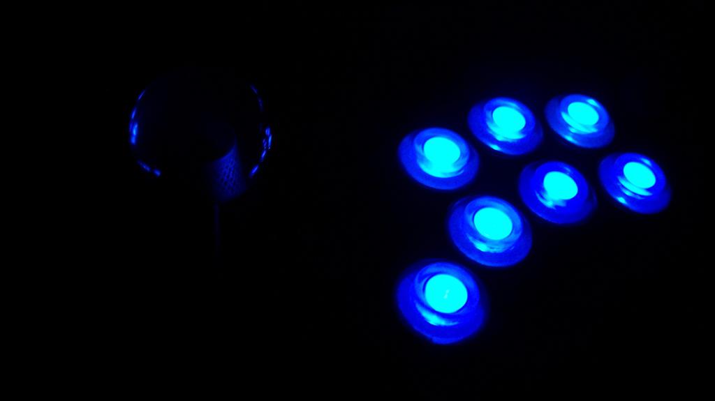
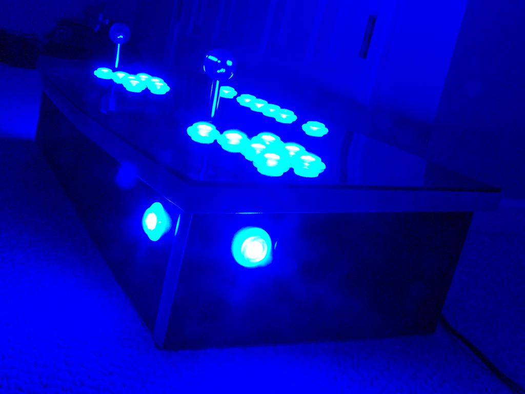
On the bottom of each button, I drilled 3/16" holes and press-fit LEDs into place. Current limiting resistors and power leads were soldered directly to the LEDs to connect them in parallel.
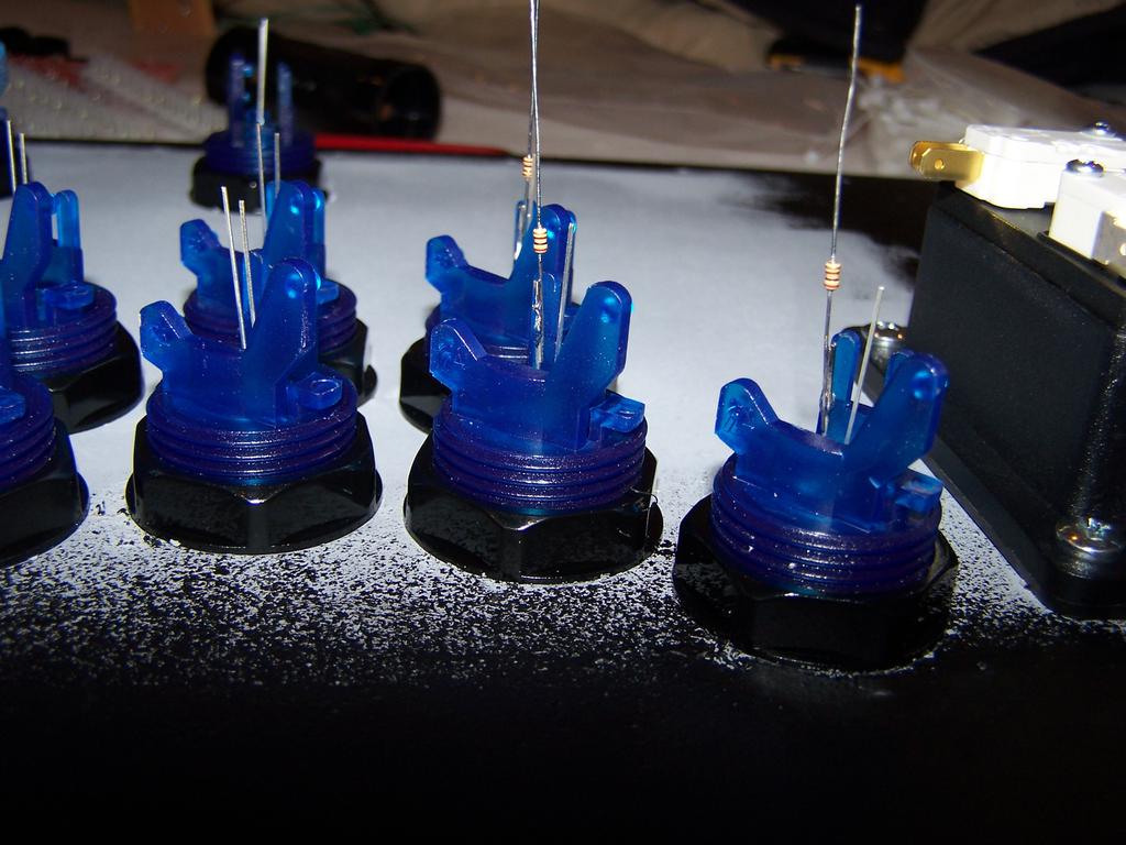
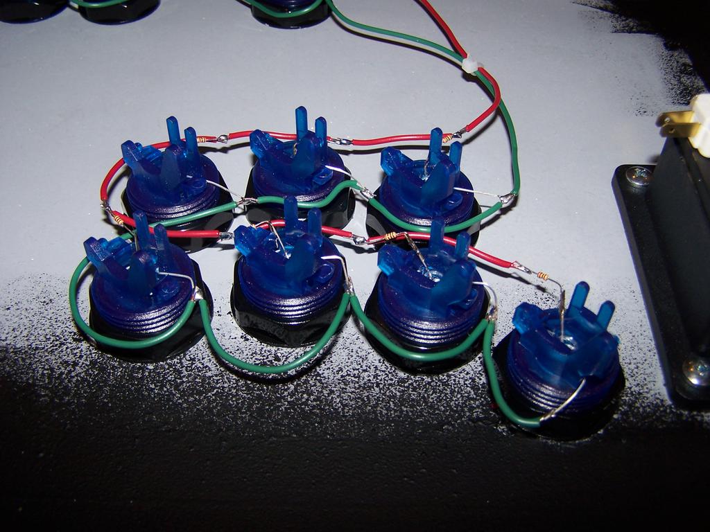
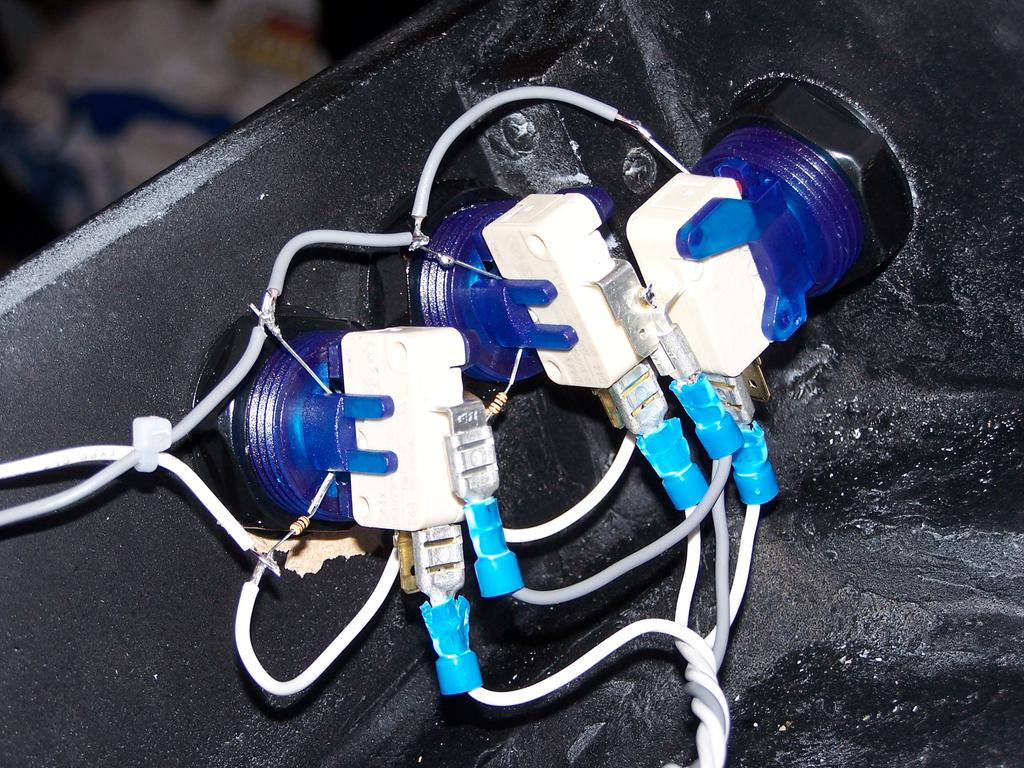
Cherry microswitches were then snapped into place and wired to the keyboard encoder using spade connectors.
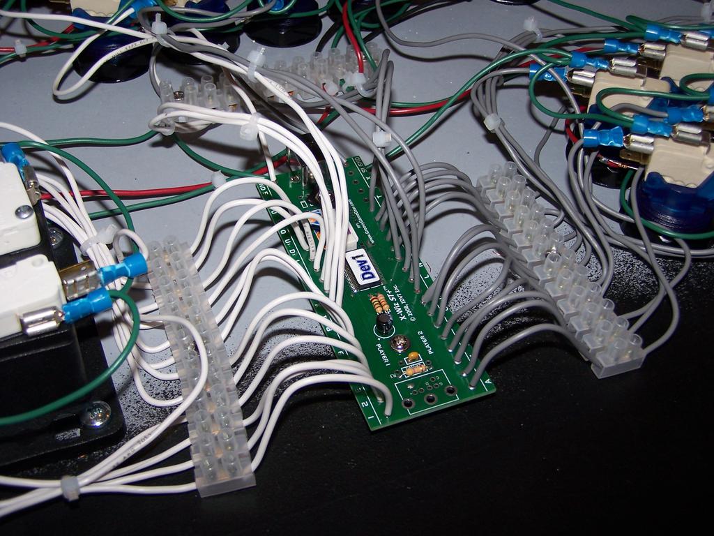
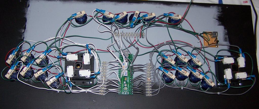
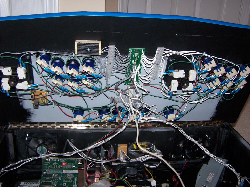
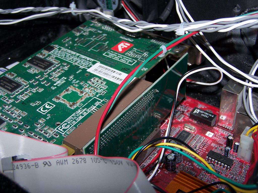
Next, I mounted the cooling fans (one blowing in, the other out) and A/V connections, and assembled the computer inside the control panel. For everything to fit, I connected the videocard (a ATI Radeon 9200) to the motherboard using a 90-degree AGP connector (and custom bracket to keep it from bouncing around in the case), and used a small flex-ATX power supply instead of a full-size ATX PSU.
Software
Note from the future: when I built this, Raspberry Pi(e)s were things that you ate, Ubuntu versions were still in the single digits, and the state of GPU-drivers and emulator support on Linux was far worse than it was on Windows, so this was built around Windows XP, with a bunch of silly hacks to make Windows disappear. If I were to do this nowadays, my choice of hardware and software would be vastly different. This thing would also weigh 10 kilos less, but I digress.
To make the whole thing seamless, I replaced the Windows XP boot screen with a custom bitmap, disabled all system sounds and unessential system services (e.g. networking), and loaded a program called MaLa instead of explorer.exe at boot.

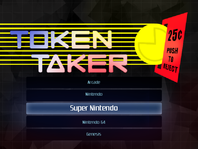
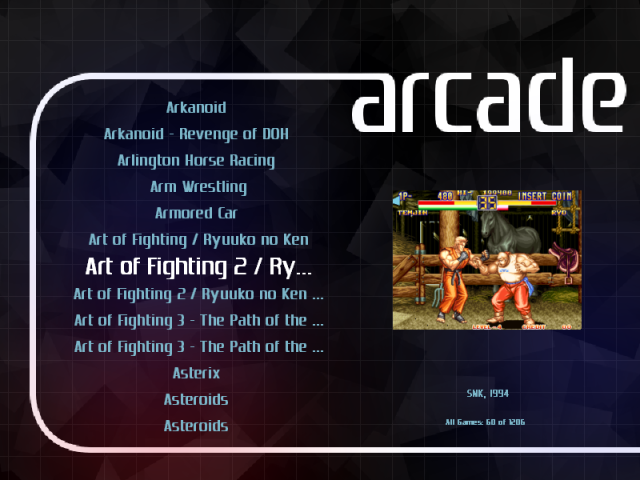
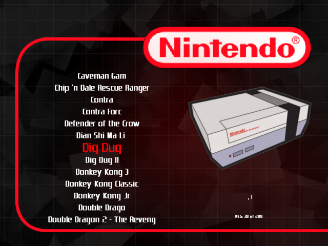
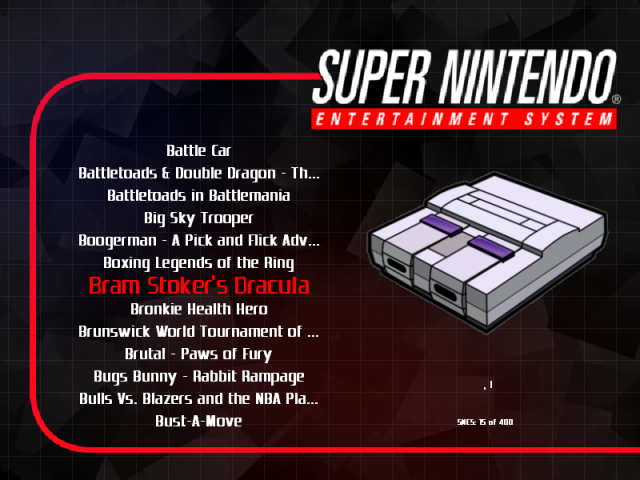
Over MaLa, the interface that I used to choose games (after choosing a game, it launched the appropriate emulator by command line), I designed a custom theme, with a main menu and separate page for each game system emulated (arcade games through MAME, and NES, SNES, Sega Genesis, N64, and Pinball through various other emulators):

Results
To leave a comment below, sign in using Github.