Making a new cross-slide for the Atlas 618 lathe
And a few additional updates and repairs for a $100 find.
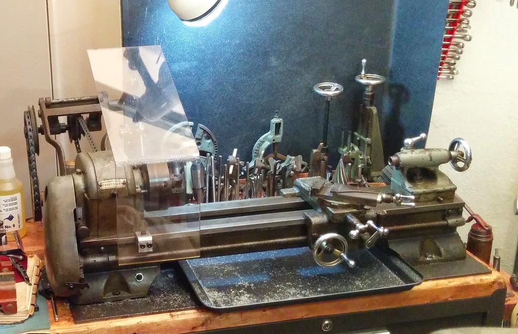
A while back, I picked up this lathe, along with a bunch of tooling, complete set of change gears, accessories (including a milling attachment!), original paperwork (including The Atlas Manual of Lathe Operations) and a substantial chunk of bronze for $100; another lucky score! Thankfully, it had been treated fairly well over the years, and didn't need much more than a wipe and an oiling before being put back to work.
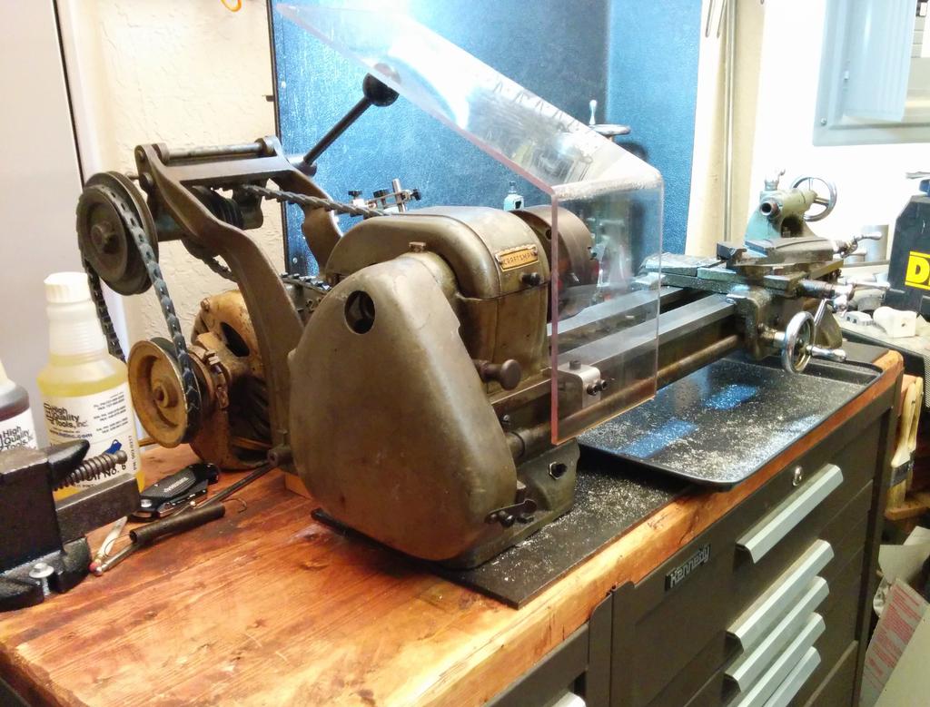
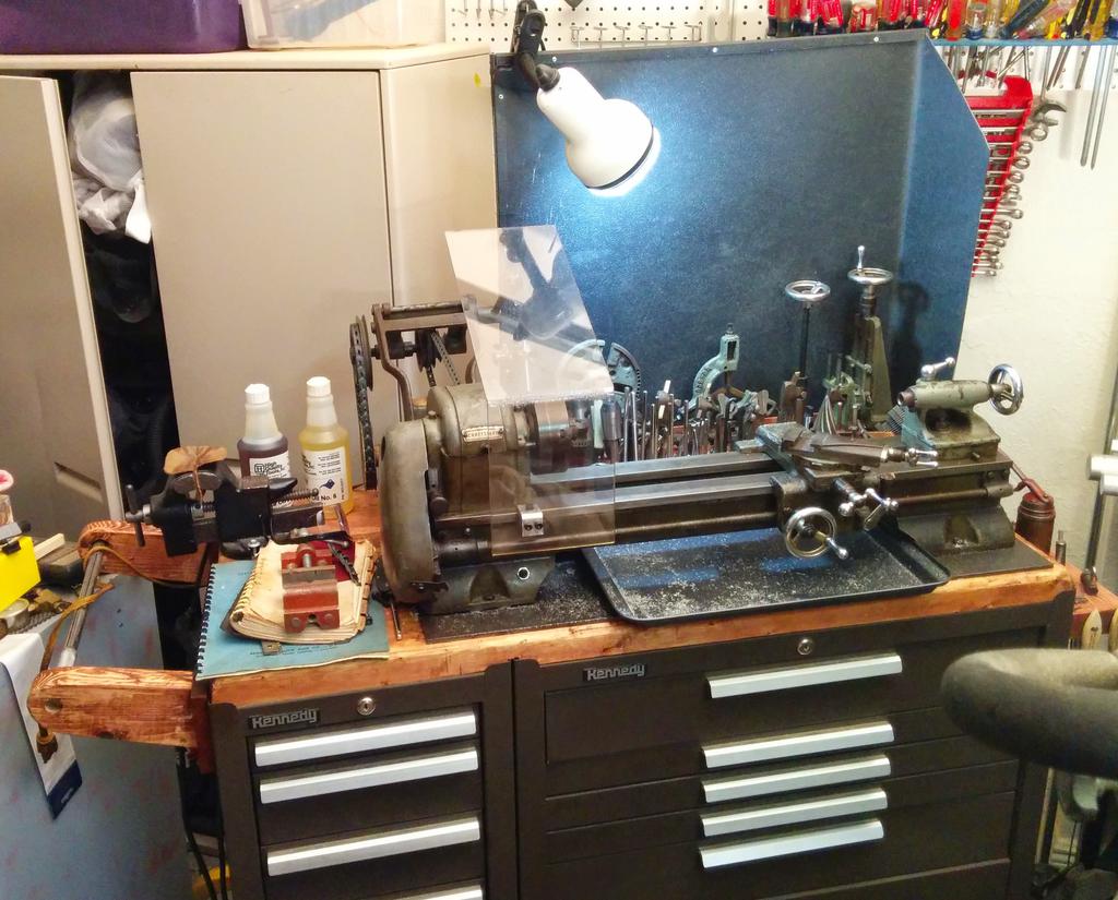
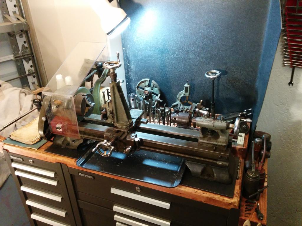
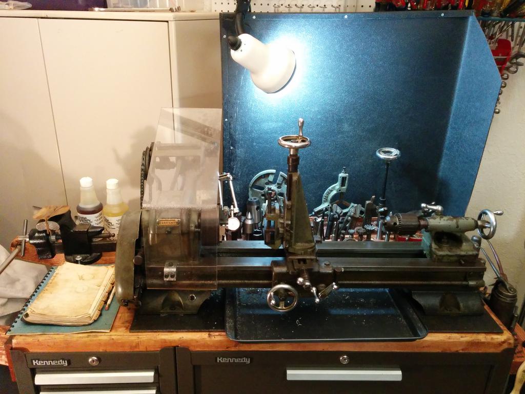
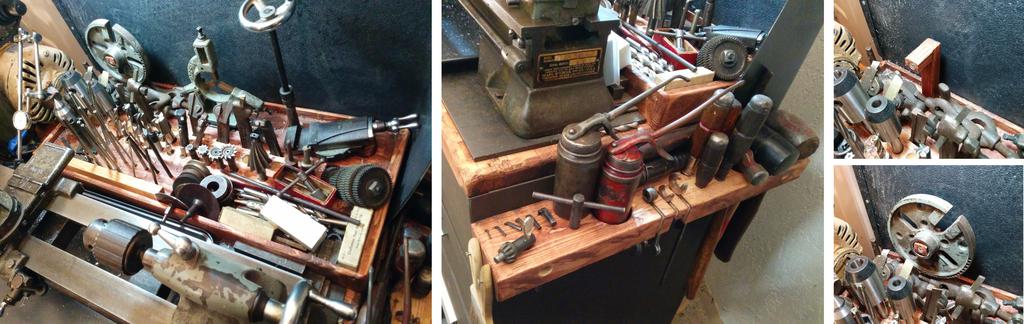
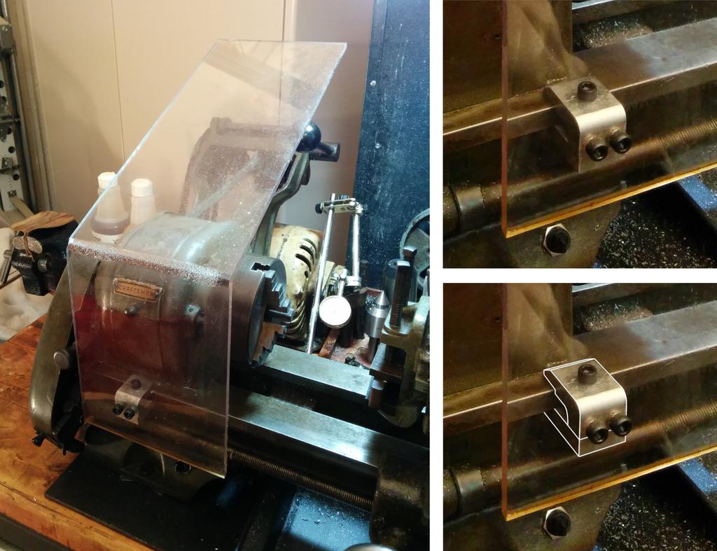
After making a few accessories, like a butcher-block top to mount it to, some tool organizers and trays for the tooling, and a chuck guard for safety, I finally turned a few parts that weren't destined for use on the lathe itself. These came out well, but while making them, I picked up on a few problems with the lathe that I had initially missed—ones that would need to be fixed before using it for much else.
Carriage Drive Gear
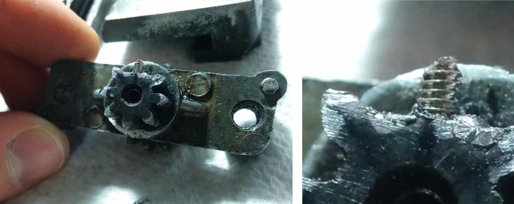
The first problem I noticed was with the carriage handwheel. Occasionally, when turning the carriage handwheel, it would slip a fraction of a turn and fail to move the carriage. As the bed-mounted rack was in perfect shape, I removed the carriage to have a look at the gears behind the apron that mesh with it—sure enough, the 8-tooth drive gear was missing almost an entire tooth.
First, I tried to find a replacement for the entire carriage-handwheel gear-reduction assembly (two small gears pressed onto a common shaft that passes through a small housing), but didn't have much luck—apparently, this was a frequently broken part, and any remaining back-stock has long since run out.
Next, I considered replacing only the gear in question, but given it's composition (Zamak, an unweldable and notoriously difficult to repair pressure die-cast Zn/Al/Mg/Cu alloy), I feared that trying to press it out of the assembly would damage the other two pieces (also made from Zamak), making the situation even worse.
At this point, I figured that trying to repair it in-place was my best-bet—if it didn't work, at worst, I'd either cut off the little gear and make a replacement to fit with what remained of the assembly, or I'd fabricobble a replacement for the whole assembly. Luckily, the repair worked.
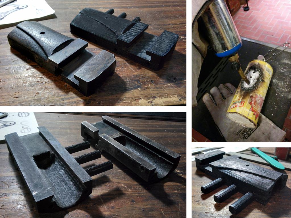
Here's how I went about it:
At the base of the tooth, I drilled and tapped a small hole, screwed in a small set screw so that it stuck out about as much as the original tooth, and filed it to fit within the original tooth profile.
Using a torch to heat the gear, I built up the area around the screw using silver solder.
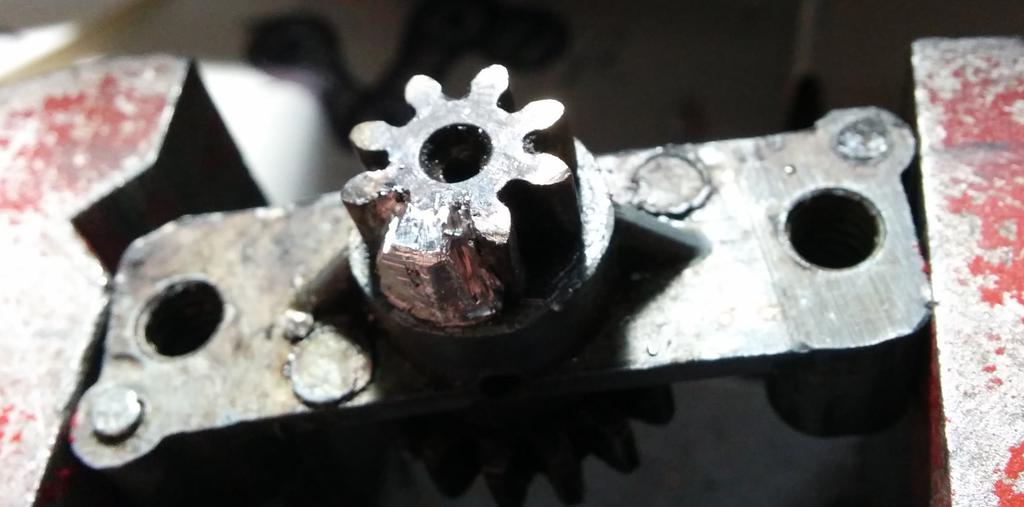
Using the other teeth as a visual guide, I filed any excess silver solder away, replicating the original profile as closely as possible.
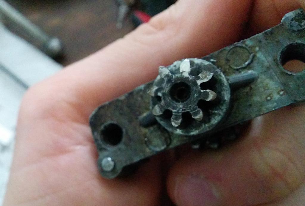
After repairing the gear, I reinstalled the assembly and tested it out. After several months of using it this way, I haven't experienced any additional problems. While this may not be the ideal technique for high-load or high-RPM gear-trains, It's a great one to have under the belt for situations like these.
Cross Slide
The next problem that I noticed—and a much more substantial one than the first—was a large crack in the cross slide (all the way across the t-slot) that the previous owner apparently tried to repair using something akin to J-B Cold Weld. This held-up for the first few parts I made, but eventually broke.
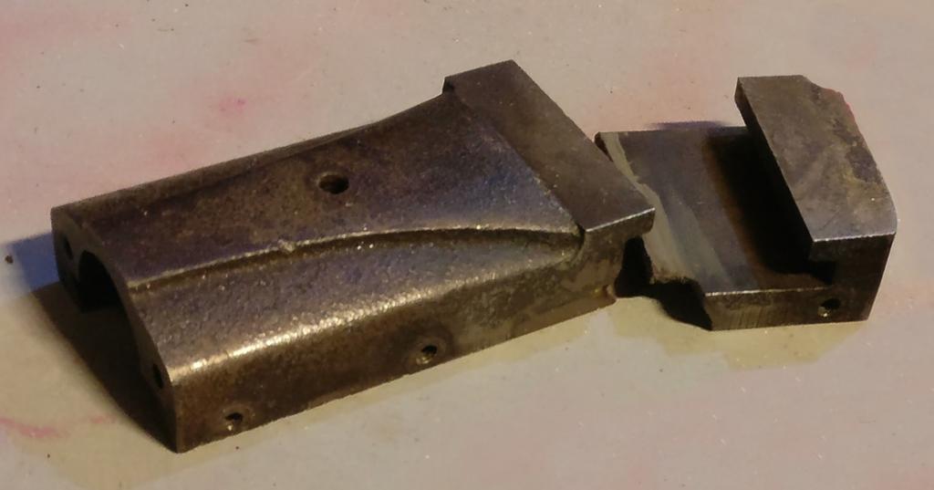
Like many other parts on the Atlas, this too was made from Zamak, and given the state of the part–broken and chipped—the only reasonable solution was to replace it outright. Also like those other parts, the only available replacements cost several times what I spent for the entire lathe—*not gonna happen*.
Attempt 1: Casting
First off, I thought it would be fun to cast a replacement from aluminum, having only just heard about lost-PLA casting and having never cast a metal part.
In lost-PLA casting, as in other forms of investment casting, you create a pattern, cast a mold around it using some form of refractory, burn or melt away the pattern, and pour molten metal into the mold to take its place. Then, once the metal casting has solidified, you break the mold to retrieve it.
There are many variables at play, and traditionally, due to the difficulty of understanding and predicting their interplay, it has oft been viewed as more of a craft than a science. Before going though with it, I knew enough to oversize my pattern to account for shrinkage, and to ensure that my mold had dried sufficiently before casting to prevent explosive decomposition, but not enough to, for example, fashion a large enough pouring basin to create a pressure head adequate to completely fill the mold, to heat the aluminum enough for it not to cool before making it past the sprues, or to size and position the sprues properly to allow for venting. All good to know for next time!
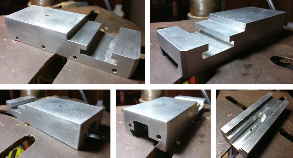
Attempt 2: Milling
Having already dedicated too much time to the casting attempt, I changed gears and went with what I knew would work: milling a replacement. I didn't have a milling machine (and still don't, if anyone has an extra Bridgeport laying around 😉), but I did just happen to acquire a lathe that (at the moment) could only mill. What luck!
A few days later, I had the 1x 2.5
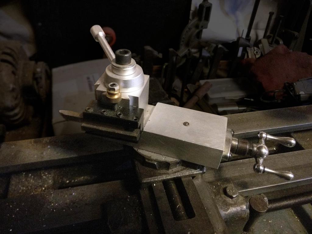
x 6" piece of 7075-T651 aluminum bar stock and Quick Change Toolpost (QCTP) in hand (which I ordered from Ebay and Amazon respectively, for ~$40 total), and got to work. As for special tooling, I bought a reground dovetail-cutter at the local flea market for a song, and got the T-slot milling cutter for free (the exact one I needed came with the lathe, along with an assortment of HSS, cobalt, and carbide endmills).
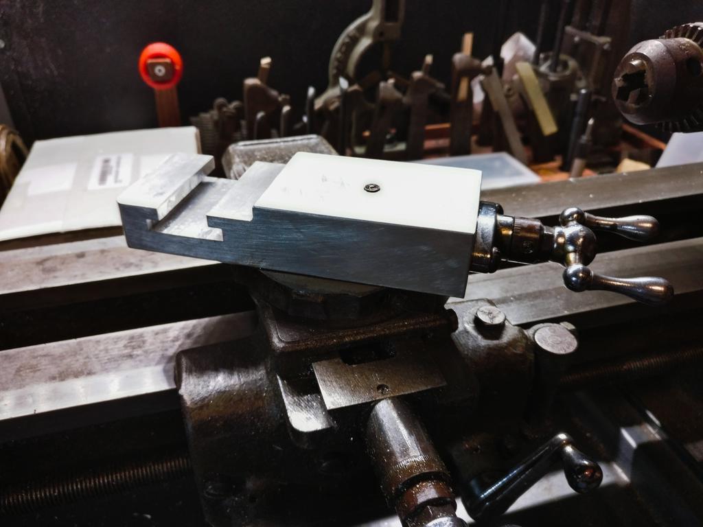
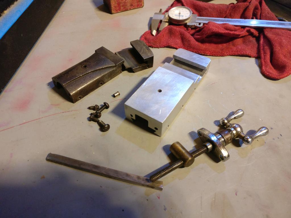
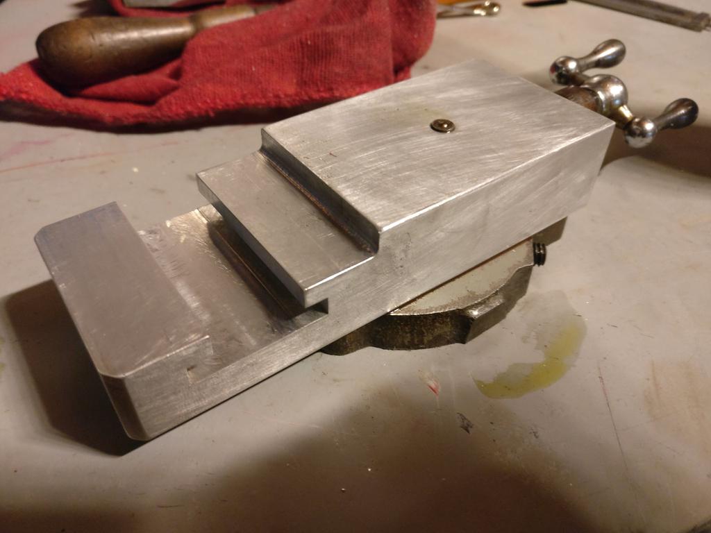
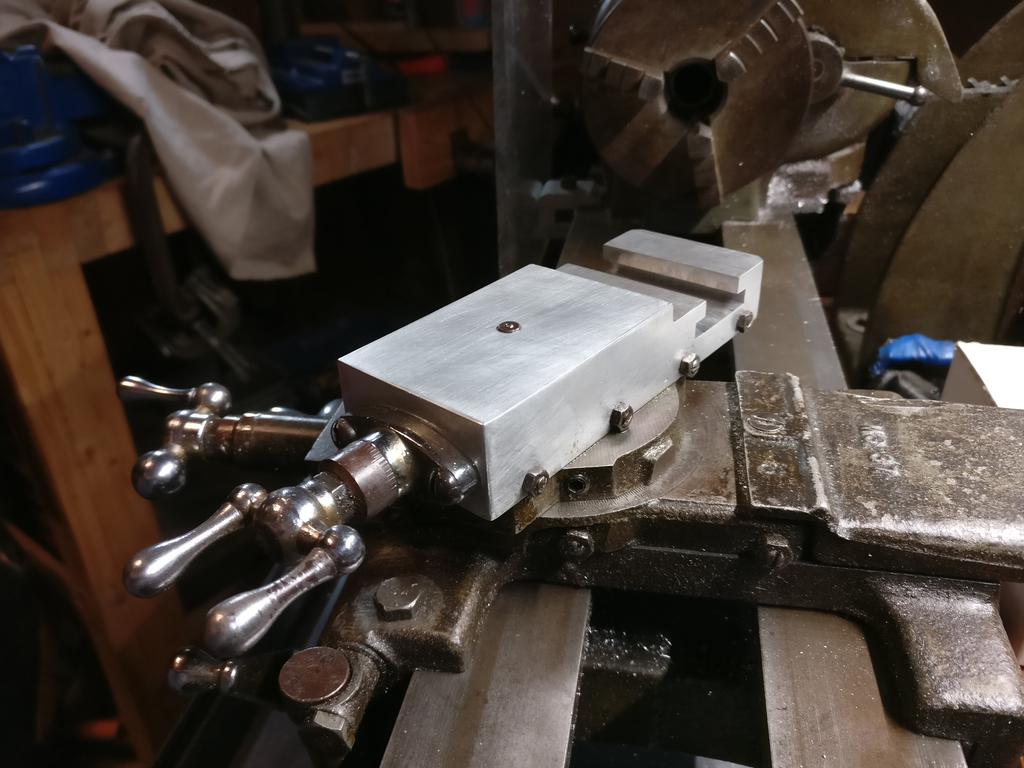
The original cross slide broke right at the intersection between the t-slot, the dovetail, and the leadscrew-channel—its weakest point. As I saw no need to copy the original part exactly (except for where tolerances are critical, like the t-slot and dovetail), I made mine wider and bulkier to strengthen it. Between the structural changes and the alloy used, I doubt I could break the new part without breaking everything around it first.
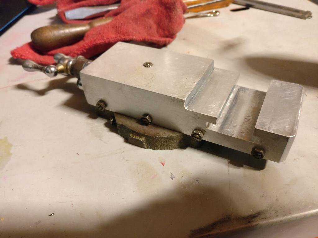
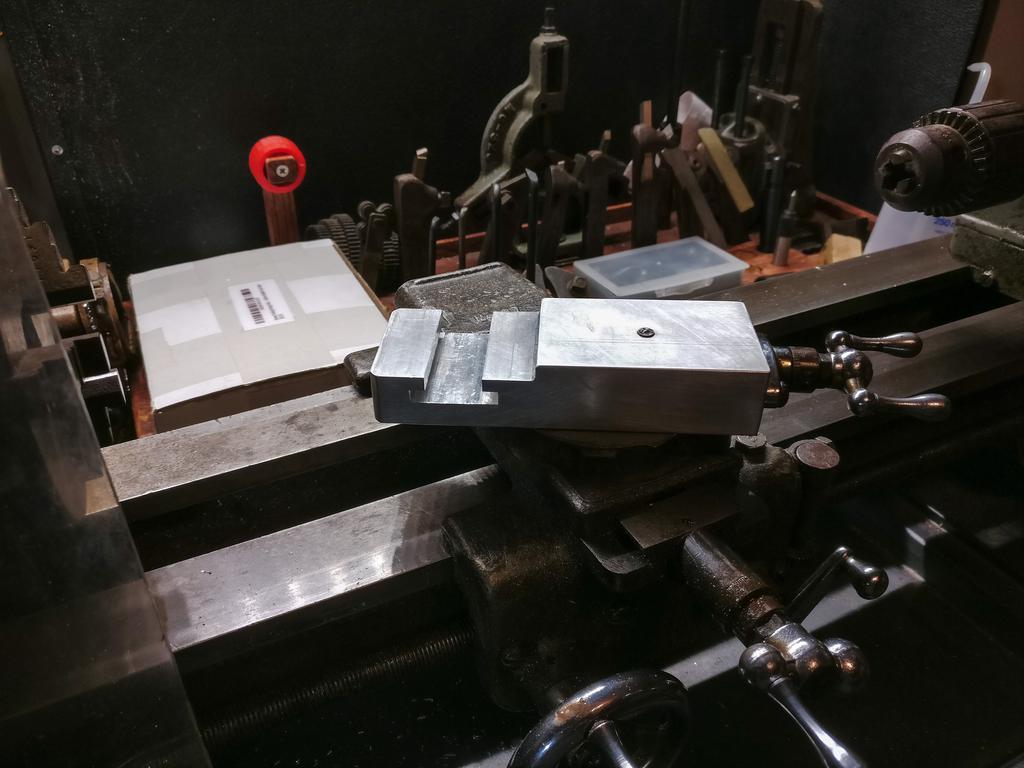
Finally, I fitted the gibbs, gibbs screws, oil nipple, and leadscrew/handwheel assembly to it, and mounted it to the lathe. Better than new!
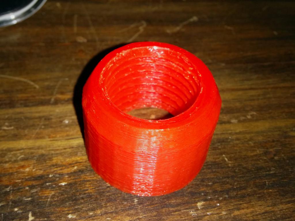
Before I go, there's actually one more small accessory I made for the lathe (so far)—a spindle thread protector for use while milling (when the chuck isn't mounted to the spindle). If you'd like to download it, head over to Thingiverse.
Thanks for reading!
To leave a comment below, sign in using Github.