Like many of my other projects, this too started as a gift. My dad has been looking for a large, interesting clock to go on the wall of his office for a long time now; this is for him.
I originally wanted to make the clock appear to be a large, solid wooden board—about one foot high and two feet wide—with the time shining through the wood itself, but determined that a layer of wood so thin, over such a broad area, would be too fragile for me to gift. Alternatively, I considered using a thin sheet of veneer (possibly backed by a hidden layer of acrylic for support), but feared this would look cheesy, and eventually, begin to peel. And either option, it seemed, would risk being too dim to view clearly during the day.
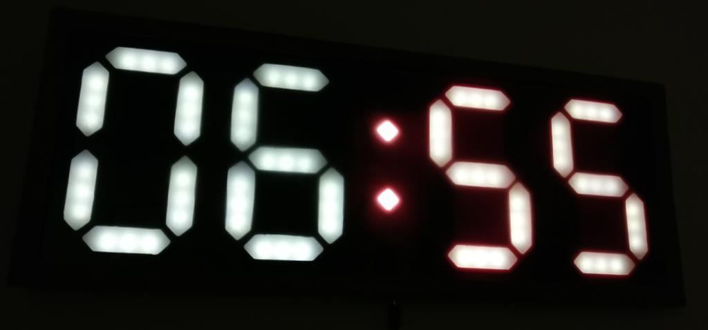
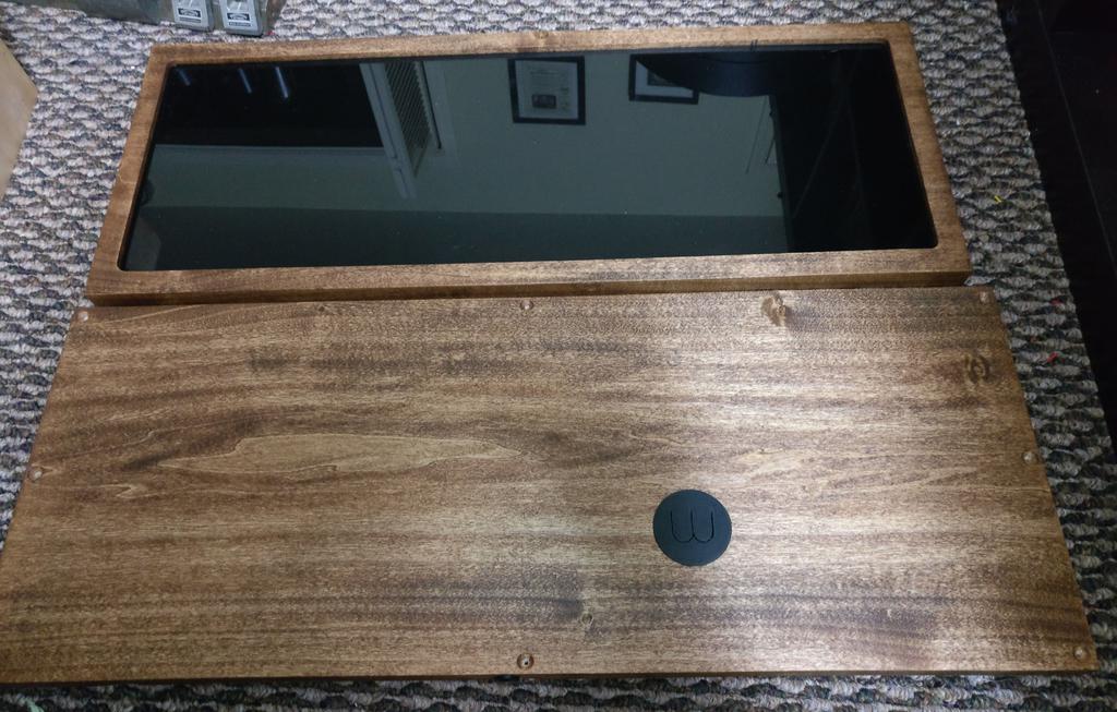
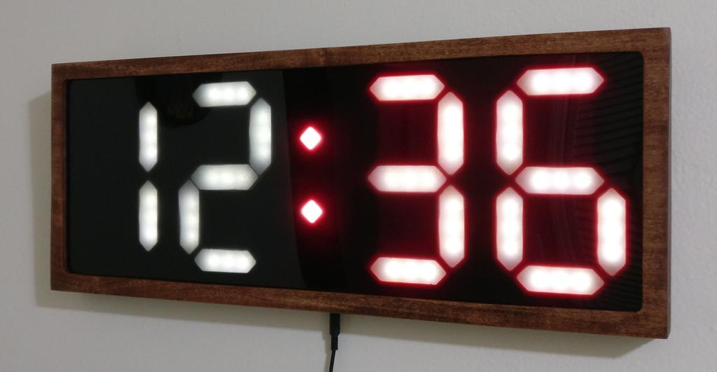
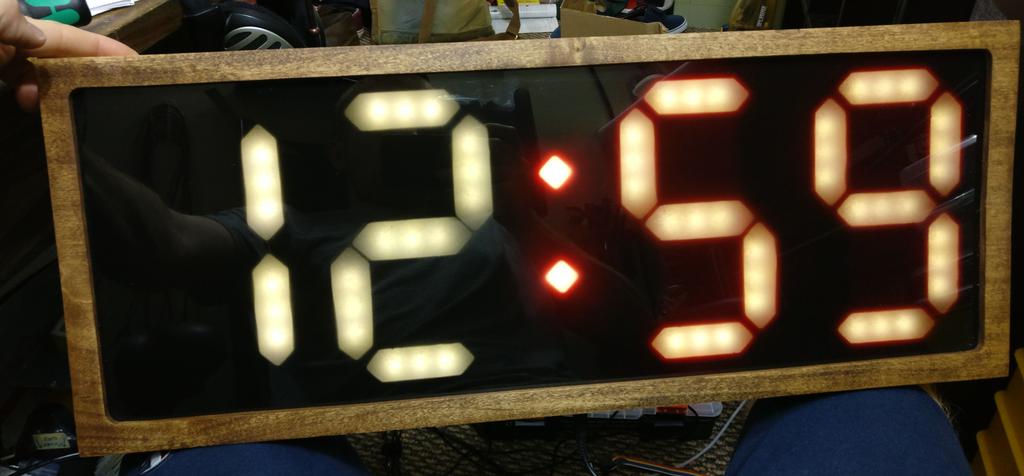
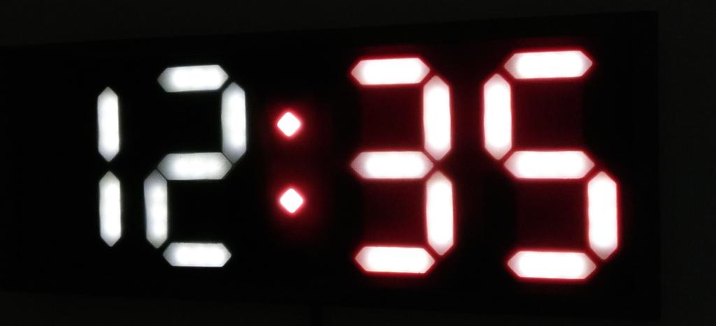
In the end, I decided upon a body and frame of wood, of the same dimensions I had originally envisioned, but with a face made of black acrylic. It would be a digital clock, with four digits, a colon, and nothing else.
Digits
To have digits as large as I wanted, I needed to make them myself. I decided to use 2-inch-long, 3-LED segments cut from white 3528 SMD LED strip for each digit segment, and 2 of the LEDs from the strip for the colon.
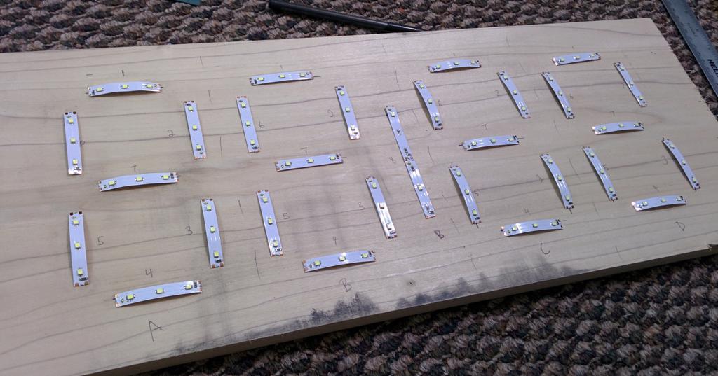
After laying these out on the wood to get a better feel of how I should size and space the digits, I put together an SVG of the layout using Inkscape, printed it out, and laid it on the wood again as a sanity check.
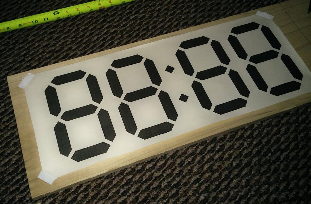
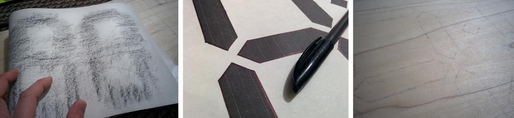
As I still wasn't sure how much space I wanted to leave around the digits when routing the cavity for the internals of the clock, and thought it would be easier to make that decision without the paper in the way, I wanted to transfer the outline of the digits and colon to the wood directly, without much work. After thinking for a minute about the best way to go about this, I grabbed a piece of charcoal, rubbed it across the back of the printout, taped the printout the the board, and traced the outline of the digits using a pen, transferring some of the carbon beneath it to the board.
After deciding how much space to leave myself for wiring each digit, I needed a way to mask the light coming from each segment of LED strip, such that it could not bleed over from one segment to the next before reaching the acrylic. I also needed to ensure that the LEDs would be spaced far enough away from the acrylic to adequately diffuse.
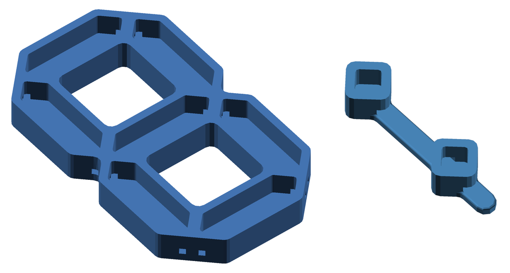
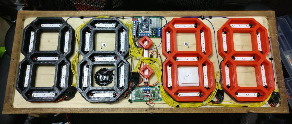
After a quick experiment with a bit of paper and cardboard, I designed the light masks in CAD and 3D printed them. As the LEDs did not grow noticeably hot in testing, even when lit continuously for several hours, I printed them using PLA.
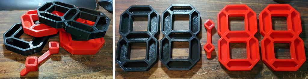
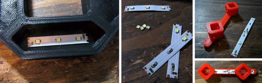
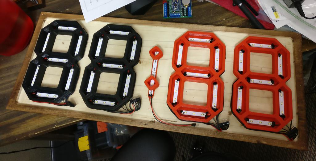
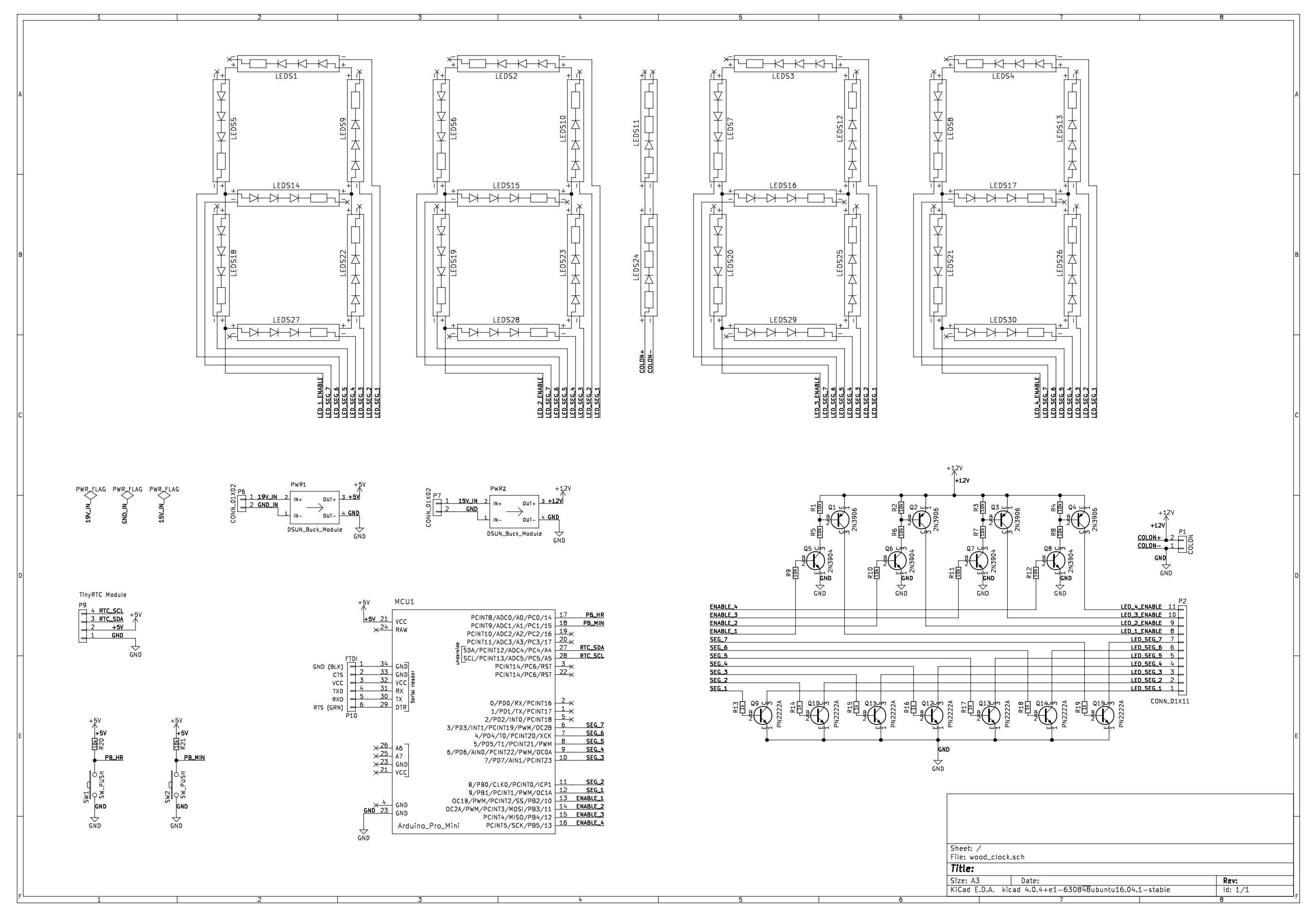
Once the light masks were printed, I adhered the LED strips to the inside of each segment (the strips are self-adhesive), routed the wires, and soldered them as below. Each digit is wired common-anode (the positive terminals each segment are daisy-chained together), with the anode acting as a 'digit enable' line for the digit, and with all cathodes, acting as 'segment enable' lines, routed separately. As a result, each digit uses a single 8-pin connector.
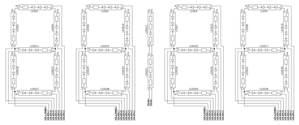
To reinforce and insulate the solder joints (and supplement the LED strip adhesive, which was not very strong), I added globs of black hot-glue (visible within the red digits below).
Digit Drivers
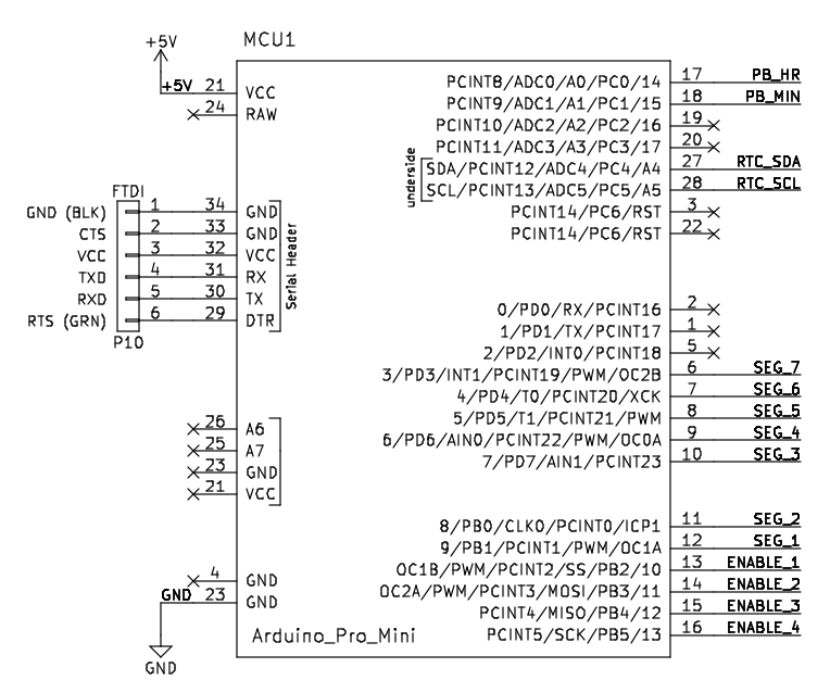
To keep things simple, I wanted to use an Arduino Pro Mini clone, of which I had several sitting unused. As it doesn't have 32 available outputs, I would need to get creative to drive all of the digits and segments.
Furthermore, in testing, each 3-LED segment stably drew around 16 mA when powered continuously at 12 V. Each digit, thus, draws a maximum of around 112 mA when all segments are lit), so little Pro Mini wouldn't be able to source enough current on its own to drive all of the digits either.
Instead of independently controlling the digits, which I couldn't do anyway without more I/Os or additional ICs, I decided to multiplex them and control them sequentially: lighting one digit for a specified period of time, then turning it off and iterating through the rest. Given how fast this happens, flicker fusion has no trouble creating the illusion of persistence.
To do this, we require only one 'digit enable' line for each digit (the anodes, 4 total) and 7 'segment enable' lines (shared between digits), using a total of 11 signal pins (which we do have available). To ensure that enough current could be sourced, I switched each digit with a high side switch, consisting of a 2N3906 (PNP BJT) driven by a 2N3904 (NPN BJT, required as the load voltage is higher than the signal voltage), and each segment with a PN2222 (NPN BJT) acting as a low side switch.
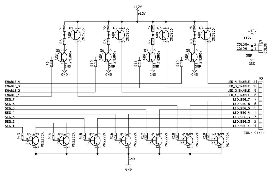
The colon is connected directly to power and is not switched.
Buttons
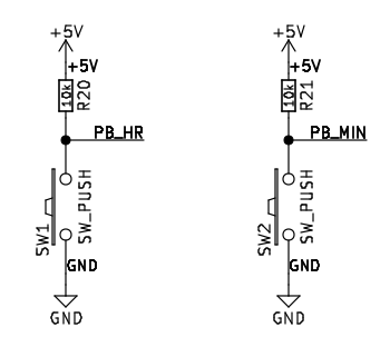
As I'm giving this as a gift, I wanted it to have a minimal interface—a proper gift should never make the recipient's life more difficult. Like most clocks, when power is cut and restored, the time resets to 12:00:00. For changing the time, when necessary, only two buttons are provided: one for hours and one for minutes. Neither a power switch nor a button for adjusting seconds is provided, though the time may be synced with another clock by plugging the clock in at just the right time.
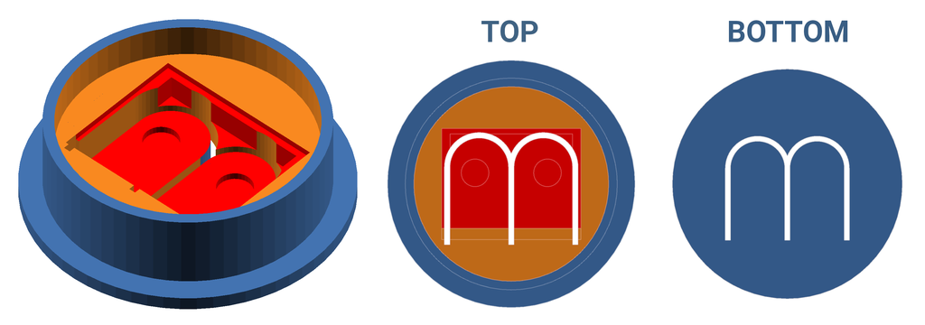

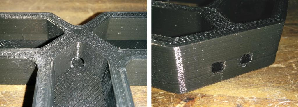
The two buttons used to adjust the time were mounted to a small piece of perfboard, which is encased in a 3D-printed casing (and sealed from behind with flexible black hot-glue), providing a degree of protection to the buttons and a more pleasant interface to interact with. This is mounted into the back of the clock.
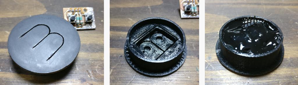
The buttons act as pulldowns, and are debounced in software. Pressing a button once increments the corresponding value (minutes or seconds) by one, and holding the button continues to increment it (at a quick but easily controllable rate).
Microcontroller
As mentioned above, I used an Arduino Pro Mini. While I originally planned to use a real-time-clock (RTC) module for time-keeping, the module that arrived was DOA. To have the clock ready for when I planned to gift it, I instead used the Arduino's internal frequency reference as the clock, and calibrated it over the next few days against the official NIST US time, accounting for drift by incrementing or decrementing a counter (adding a second every 2010 s, and then subtracting a second every 16 hours). It has proven to keep time very closely after calibrating it in this way.
Code

##include <TimeLib.h>

##define DISPLAY_BRIGHTNESS  4000 // (time in us to light each digit before switching to the next)

const int digit1 = 10;
const int digit2 = 11;
const int digit3 = 12;
const int digit4 = 13;

const int seg1 = 9;
const int seg2 = 8;
const int seg3 = 7;
const int seg4 = 6;
const int seg5 = 5;
const int seg6 = 4;
const int seg7 = 3;

const int hrButton = 14;
const int minButton = 15;

int hrButtonCtr = 0;
int minButtonCtr = 0;

long lastTimeAdjLarge = 0;
long lastTimeAdjSmall = 0;

void setup()
{
  pinMode(seg1, OUTPUT);
  pinMode(seg2, OUTPUT);
  pinMode(seg3, OUTPUT);
  pinMode(seg4, OUTPUT);
  pinMode(seg5, OUTPUT);
  pinMode(seg6, OUTPUT);
  pinMode(seg7, OUTPUT);

  pinMode(digit1, OUTPUT);
  pinMode(digit2, OUTPUT);
  pinMode(digit3, OUTPUT);
  pinMode(digit4, OUTPUT);

  pinMode(hrButton, INPUT);
  pinMode(minButton, INPUT);

  setTime(12, 0, 0, 1, 1, 2017);

  lastTimeAdjLarge = millis();
  lastTimeAdjSmall = millis();
}

void loop()
{
  displayTime(int(hourFormat12()*100 + int(minute())));

  // Correct for 16 MHz crystal oscillator inaccuracy (large error, ~1 s slow every 2010 s)
  if ((millis() - lastTimeAdjLarge) > 2010000) {
    adjustTime(1);
    lastTimeAdjLarge = millis();
  } else if (millis() < lastTimeAdjLarge) {
    lastTimeAdjLarge = millis();
  }
    // Correct for 16 MHz crystal oscillator inaccuracy (small error, ~1 s fast every 16 hr)
  if ((millis() - lastTimeAdjSmall) > 57600000) {
    adjustTime(-1);
    lastTimeAdjSmall = millis();
  } else if (millis() < lastTimeAdjSmall) {
    lastTimeAdjSmall = millis();
  }

  // Button must be depressed for more than 10 consecutive iterations to adjust hrs
  if (digitalRead(hrButton) == 0) {
    hrButtonCtr += 1;
    if (hrButtonCtr > 10) {
      adjustTime(3600);
      hrButtonCtr = 0;
    }
  } else {
    hrButtonCtr = 0;
  }

  // Button must be depressed for more than 10 consecutive iterations to adjust mins
  if (digitalRead(minButton) == 0) {
    minButtonCtr += 1;
    if (minButtonCtr > 10) {
      adjustTime(60);
      minButtonCtr = 0;
    }
  } else {
    minButtonCtr = 0;
  }

}

void lightNumber(int numberToDisplay)
{
  switch (numberToDisplay)
  {
    case 0:
      digitalWrite(seg1, HIGH);
      digitalWrite(seg2, HIGH);
      digitalWrite(seg3, HIGH);
      digitalWrite(seg4, HIGH);
      digitalWrite(seg5, HIGH);
      digitalWrite(seg6, HIGH);
      digitalWrite(seg7, LOW);
      break;
    case 1:
      digitalWrite(seg1, LOW);
      digitalWrite(seg2, HIGH);
      digitalWrite(seg3, HIGH);
      digitalWrite(seg4, LOW);
      digitalWrite(seg5, LOW);
      digitalWrite(seg6, LOW);
      digitalWrite(seg7, LOW);
      break;
    case 2:
      digitalWrite(seg1, HIGH);
      digitalWrite(seg2, HIGH);
      digitalWrite(seg3, LOW);
      digitalWrite(seg4, HIGH);
      digitalWrite(seg5, HIGH);
      digitalWrite(seg6, LOW);
      digitalWrite(seg7, HIGH);
      break;
    case 3:
      digitalWrite(seg1, HIGH);
      digitalWrite(seg2, HIGH);
      digitalWrite(seg3, HIGH);
      digitalWrite(seg4, HIGH);
      digitalWrite(seg5, LOW);
      digitalWrite(seg6, LOW);
      digitalWrite(seg7, HIGH);
      break;
    case 4:
      digitalWrite(seg1, LOW);
      digitalWrite(seg2, HIGH);
      digitalWrite(seg3, HIGH);
      digitalWrite(seg4, LOW);
      digitalWrite(seg5, LOW);
      digitalWrite(seg6, HIGH);
      digitalWrite(seg7, HIGH);
      break;
    case 5:
      digitalWrite(seg1, HIGH);
      digitalWrite(seg2, LOW);
      digitalWrite(seg3, HIGH);
      digitalWrite(seg4, HIGH);
      digitalWrite(seg5, LOW);
      digitalWrite(seg6, HIGH);
      digitalWrite(seg7, HIGH);
      break;
    case 6:
      digitalWrite(seg1, HIGH);
      digitalWrite(seg2, LOW);
      digitalWrite(seg3, HIGH);
      digitalWrite(seg4, HIGH);
      digitalWrite(seg5, HIGH);
      digitalWrite(seg6, HIGH);
      digitalWrite(seg7, HIGH);
      break;
    case 7:
      digitalWrite(seg1, HIGH);
      digitalWrite(seg2, HIGH);
      digitalWrite(seg3, HIGH);
      digitalWrite(seg4, LOW);
      digitalWrite(seg5, LOW);
      digitalWrite(seg6, LOW);
      digitalWrite(seg7, LOW);
      break;
    case 8:
      digitalWrite(seg1, HIGH);
      digitalWrite(seg2, HIGH);
      digitalWrite(seg3, HIGH);
      digitalWrite(seg4, HIGH);
      digitalWrite(seg5, HIGH);
      digitalWrite(seg6, HIGH);
      digitalWrite(seg7, HIGH);
      break;
    case 9:
      digitalWrite(seg1, HIGH);
      digitalWrite(seg2, HIGH);
      digitalWrite(seg3, HIGH);
      digitalWrite(seg4, HIGH);
      digitalWrite(seg5, LOW);
      digitalWrite(seg6, HIGH);
      digitalWrite(seg7, HIGH);
      break;
    default:
      digitalWrite(seg1, LOW);
      digitalWrite(seg2, LOW);
      digitalWrite(seg3, LOW);
      digitalWrite(seg4, LOW);
      digitalWrite(seg5, LOW);
      digitalWrite(seg6, LOW);
      digitalWrite(seg7, LOW);
      break;
  }
}

void displayTime(int toDisplay)
{
  for(int digit = 4 ; digit > 0 ; digit--)
  {
    switch(digit)
    {
      case 1:
        digitalWrite(digit1, HIGH);
        digitalWrite(digit2, LOW);
        digitalWrite(digit3, LOW);
        digitalWrite(digit4, LOW);
        break;
      case 2:
        digitalWrite(digit1, LOW);
        digitalWrite(digit2, HIGH);
        digitalWrite(digit3, LOW);
        digitalWrite(digit4, LOW);
        break;
      case 3:
        digitalWrite(digit1, LOW);
        digitalWrite(digit2, LOW);
        digitalWrite(digit3, HIGH);
        digitalWrite(digit4, LOW);
        break;
      case 4:
        digitalWrite(digit1, LOW);
        digitalWrite(digit2, LOW);
        digitalWrite(digit3, LOW);
        digitalWrite(digit4, HIGH);
        break;
    }

    // Display one digit of 'toDisplay' at a time, from LSD to MSD
    lightNumber(toDisplay % 10);
    toDisplay /= 10;

    // Hold each digit lit for 'DISPLAY_BRIGHTNESS' before lighting next
    delayMicroseconds(DISPLAY_BRIGHTNESS);

    // Clear digits and segments to prevent ghosting
    digitalWrite(digit1, LOW);
    digitalWrite(digit2, LOW);
    digitalWrite(digit3, LOW);
    digitalWrite(digit4, LOW);
    lightNumber(10);
  }
}
Putting it all Together
In front of the digits masks are two layers of parchment paper and two layers of black acrylic. I had originally planned to use only one layer of black acrylic, it was a little too transparent for my liking, and two layer was not quite diffuse enough. While playing around with what else I might diffuse the light with, I tried parchment paper, and really like the look of it; it gives the light a bit of a textured, worn, and slightly rippled look.
Resources
Full Schematic
Additional Files
Images
Digit/Colon Layout SVG:

CAD Files
- Single Digit Light Mask [STL], designed using PTC Creo in June, 2016.
- Colon Light Mask [STL], designed using PTC Creo in June, 2016.
- Button Cover [STL], designed using PTC Creo in June, 2016.
To leave a comment below, sign in using Github.