
We needed a pipette puller at work to test out an electrophysiology rig, but didn't have easy access to one, and didn't want to pony up multiple thousands for a commercial one just for testing. We also needed one quickly—publish or perish—and getting approval from purchasing for an expensive piece of equipment takes time, as does shipping. To get things rolling, I whipped this one together from the junk pile over a couple nights.
While another lab eventually offered to let us borrow their Sutter P-97, this one helped us get started. It isn't perfect—frankly, it's hacky as hell—but it works in a pinch.
Principles
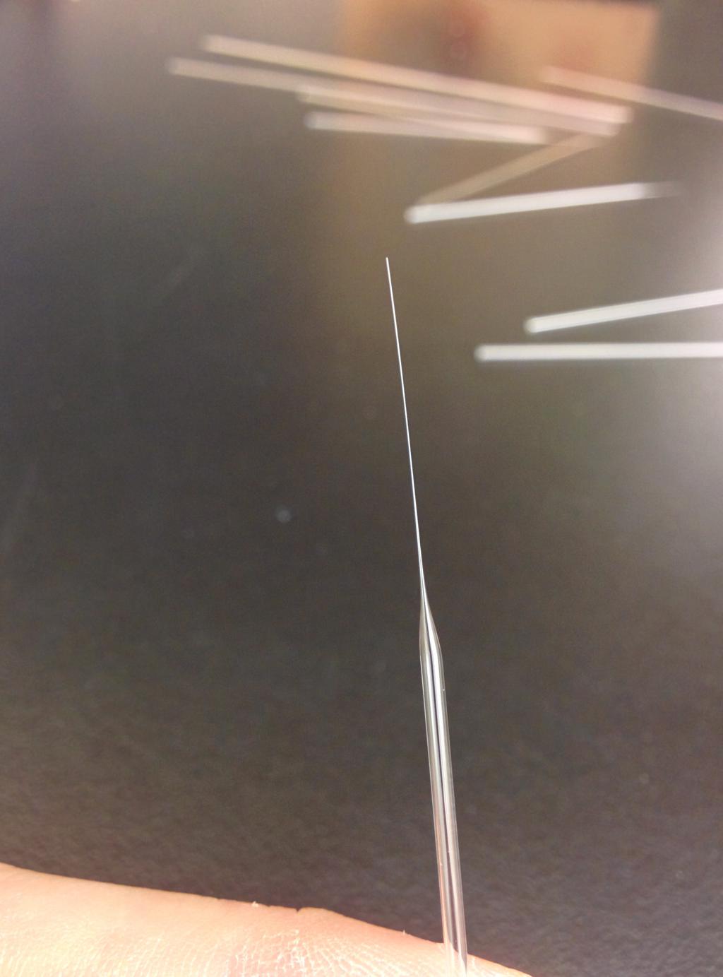
For starters, the kind of pipette I'm talking about—the kind we needed—is formed from glass microcapillary tubing, and has an open tip of 5–10 um in diameter that is plugged with a bit of agarose (if you aren't familiar, it behaves like gelatin). Our preferred tip-taper-length has not yet been determined, as we will do so through experimentation. If any of the above sounds familiar to you, these will be used for extracellular field-level recording rather than patch clamping.
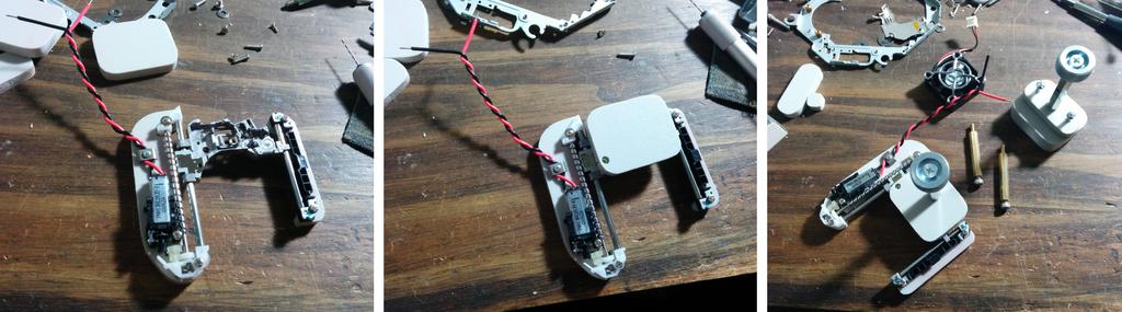
Starting with a glass microcapillary of constant inner and outer diameter (much larger than the desired tip diameter) and clamping the microcapillary at both ends, a pipette puller must heat the center to soften the glass and pull the two ends apart, drawing the center to a thin taper. Either by the act of pulling itself, or using diamond-tipped cutting pen, the microcapillary is separated into two pipettes, at the center.
When pulling a pipette, you're typically trying to match a specified tip diameter, tip taper length, and tip taper angle, and depending on the pipette puller, you may be offered a number of variables to adjust while attempting to do so. Among these include soak (preheat) and pull temperatures, soak time, pull tension, velocity, and distance, and internal air pressure (if the puller allows for it)—a tangled web of interdependent variables.
Design
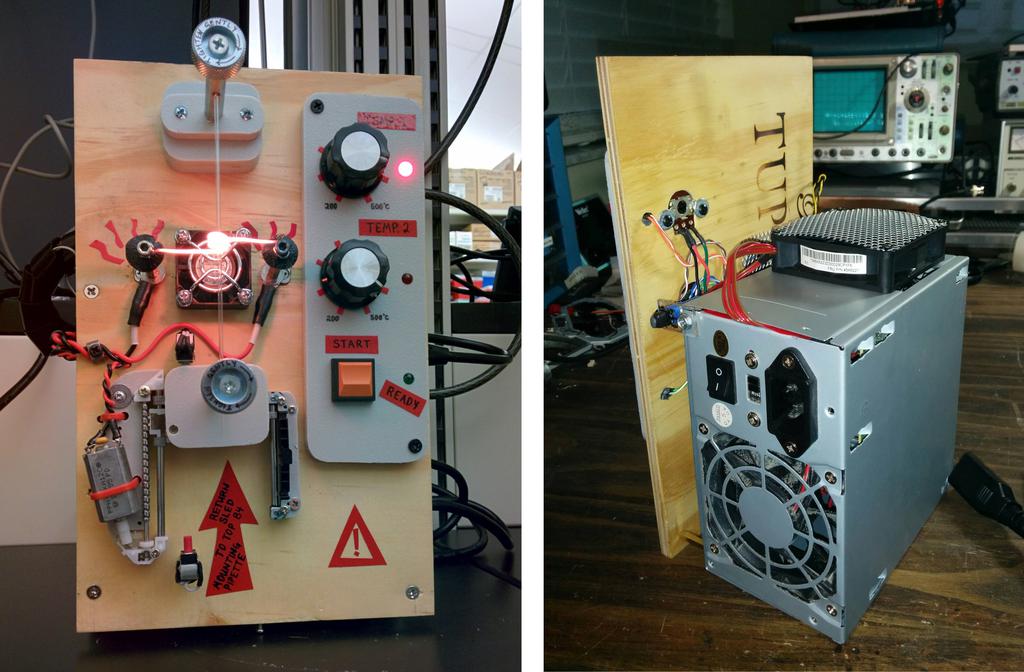
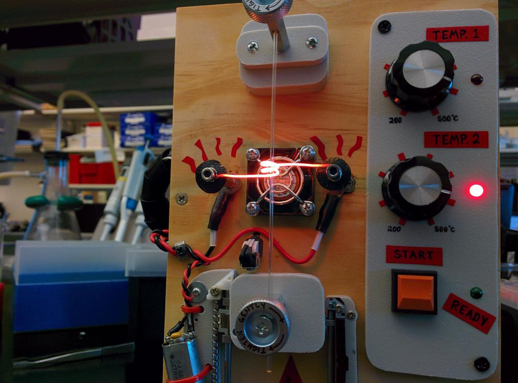
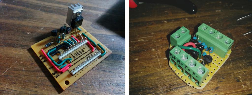
The puller I designed consists of a stationary upper microcapillary clamp, a driven lower clamp (with upper and lower limit-switches), and a nichrome-wire heater in between.
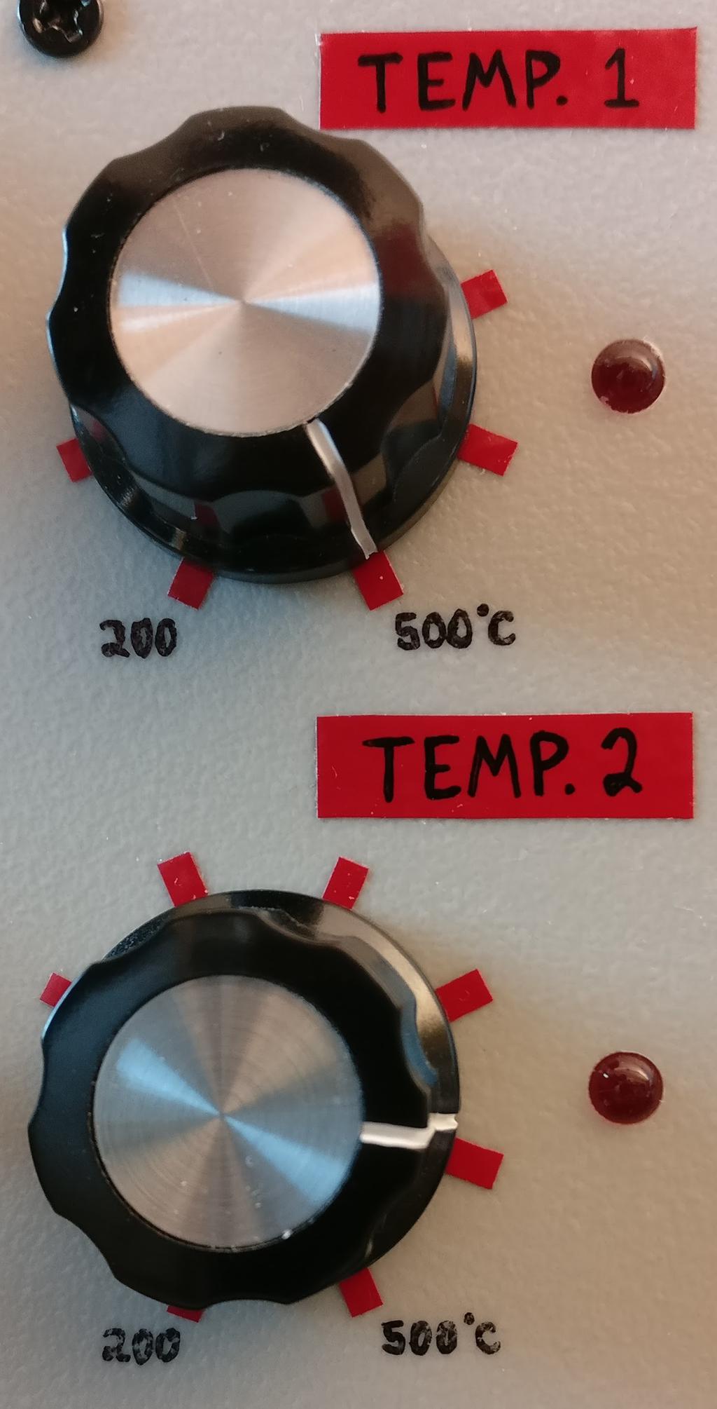
To keep things simple, I opted to allow for the adjustment of only two variables, either setting the rest constant or allowing them to vary naturally in subservience to the rest. Those variables are soak temperature and pull temperature, and can be set using the two potentiometer knobs on the front panel.
Upon powering up the device, the green READY LED is lit. After raising the lower clamp carriage to its highest position, the user inserts a glass microcapillary through the upper clamp, nichrome wire heater, and lower clamp, gently tightens both clamps, and presses the START button. In response:
The red TEMP 1 indicator LED is lit, the heater is heated to the soak temperature (TEMP 1) for thirty seconds, and the pipette is pulled gently at TEMP 1 for one second.
The TEMP 1 indicator is turned off, the red TEMP 2 indicator is lit, the heater is heated to the pull temperature for twenty seconds, and the pipette is pulled at TEMP 2 until the lower limit switch it hit.
Note: Depending on the temperatures set (and to what degree they soften the glass), the first pull might stretch the microcapillary substantially or not at all, and the second pull might stretch it immediately or after some delay, in both cases limited by torque of the small motor used.
The TEMP 2 indicator and heater are turned off, the cooling fan is run for thirty seconds and shut off, and all three indicators are flashed twice. Finally, the green READY LED is lit again.
Electronics and Code
The code is run on an Arduino Pro Mini clone, and flashed using Platformio.
platformio.ini
[env:pro16MHzatmega328]
platform = atmelavr
framework = arduino
board = pro16MHzatmega328
src/main.cpp
/*******************************************************************************
 *
 *     Thing:   Pipette puller driver
 *
 *    Author:   Garrett Goss
 *      Date:   Dec 31, 2015
 *
 *   License:   MIT, Copyright (c) 2015 Garrett Marshall Goss
 *
 ******************************************************************************/

##include "Arduino.h"

// inputs
##define POT_HEATER_1         A3
##define POT_HEATER_2         A2
##define BUTTON_LIMIT_TOP     14
##define BUTTON_LIMIT_BOTTOM  12
##define BUTTON_START          9 // timer1

// outputs
##define HEATER               10 // timer1
##define FAN                   2
##define MOTOR_FWD             5 // timer0 (along with delay and millis)
##define MOTOR_REV             6 // timer0
##define LED_HEATER_1         11 // timer2
##define LED_HEATER_2          4
##define LED_READY             8

// Flashes all LEDs a specified number of times
void indicate(int counter) {
  for (int i = 0; i < counter; i++) {
    digitalWrite(LED_READY, 1);
    digitalWrite(LED_HEATER_2, 1);
    digitalWrite(LED_HEATER_1, 1);
    delay(500);
    digitalWrite(LED_READY, 0);
    digitalWrite(LED_HEATER_2, 0);
    digitalWrite(LED_HEATER_1, 0);
    delay(500);
  }
}

// Does nothing until start button is pressed
void waitForStart() {
  while (digitalRead(BUTTON_START)) {
  }
}

// Returns (0) if either a limit switch or the start button is hit.
// Listening for the start button allows for the pulling process to be
// interrupted by the user
bool limits() {
  bool top = digitalRead(BUTTON_LIMIT_TOP); // 0 if pressed
  bool bottom = digitalRead(BUTTON_LIMIT_BOTTOM); // 0 if pressed
  bool start = digitalRead(BUTTON_START); // 0 if pressed
  bool limHit = 0;
  if (top == 0 || bottom == 0 || start == 0) limHit = 1; // 1 if pressed
  return limHit;
}

// Pull carriage downward, indefinitely or for a specified amount of time
// (milliseconds), at a specified duty cycle
void downFor(int ms) {
  digitalWrite(MOTOR_REV, 0);
  digitalWrite(MOTOR_FWD, 1);
  delay(ms);
  digitalWrite(MOTOR_FWD, 0);
}

// Pulls carriage downward until a limit switch (or the start button) is hit
void down() {
  digitalWrite(MOTOR_REV, 0);
  digitalWrite(MOTOR_FWD, 1);
  bool limHit = 0;
  while (!limHit) {
    limHit = limits();
  }
  digitalWrite(MOTOR_FWD, 0);
}

// Heats the heater to either set temperature 1 (when heaterNumber == 1)
// or to set temperature 2 (when heaterNumber == 2) for a specified amount
// of time (milliseconds). Temperatures predicted from the specifications
// of the nichrome wire used, and (roughly) validated by IR thermometer.
void heat(int heaterNumber, int ms) {
  digitalWrite(FAN, 0);
  int temp = 0;
  if (heaterNumber == 1) {
    int pot1 = analogRead(POT_HEATER_1); // 10 bit
    temp = map(pot1,0,1023,0,255);
    analogWrite(HEATER, temp);
    delay(ms);
  } else if (heaterNumber == 2) {
    int pot2 = analogRead(POT_HEATER_2); // 10 bit
    temp = map(pot2,0,1023,0,255);
    analogWrite(HEATER, temp);
    delay(ms);
  }
}

// Runs the cooling fan for a specified amount of time (milliseconds)
void coolFor(int ms) {
  analogWrite(HEATER,0);
  digitalWrite(FAN, 1);
  delay(ms);
  digitalWrite(FAN,0);
}

void setup() {
  pinMode(POT_HEATER_1, INPUT);
  pinMode(POT_HEATER_2, INPUT);
  pinMode(BUTTON_LIMIT_TOP, INPUT_PULLUP);
  pinMode(BUTTON_LIMIT_BOTTOM, INPUT_PULLUP);
  pinMode(BUTTON_START, INPUT_PULLUP);
  pinMode(3, INPUT);
  pinMode(HEATER, OUTPUT);
  pinMode(FAN, OUTPUT);
  pinMode(MOTOR_REV, OUTPUT);
  pinMode(MOTOR_FWD, OUTPUT);
  pinMode(LED_HEATER_1, OUTPUT);
  pinMode(LED_HEATER_2, OUTPUT);
  pinMode(LED_READY, OUTPUT);
}

void loop() {
  // wait for start
  digitalWrite(LED_READY, 1);
  waitForStart();

  // heat to first temperature, pull small amount
  digitalWrite(LED_READY, 0);
  digitalWrite(LED_HEATER_1, 1);
  heat(1, 30000);
  downFor(1000);

  // heat to second temperature, pull until limit switch is hit
  digitalWrite(LED_HEATER_1, 0);
  digitalWrite(LED_HEATER_2, 1);
  heat(2, 20000);
  down();
  digitalWrite(LED_HEATER_2, 0);

  // cool down
  coolFor(30000);
  indicate(2);
}
To leave a comment below, sign in using Github.