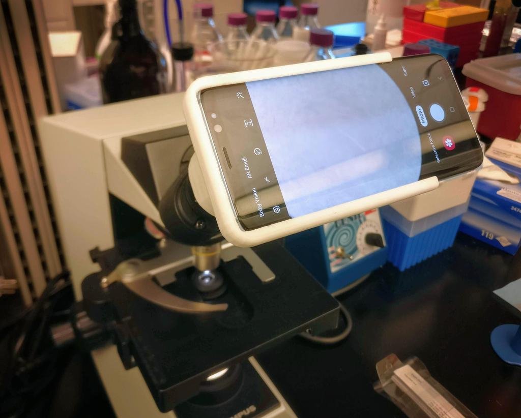
My wife's Galaxy S8 has a pretty great camera—certainly better than what you'd find on any of the microscopes in our lab. She was looking for an easy way to photograph her slides with it, so I designed this.
While I've made a more universal smartphone-microscope adapter in the past, it required a bit of fiddly adjustment when mounted to the camera before images could be captured. As my goal was to make my wife's life easier, that wouldn't be good enough.
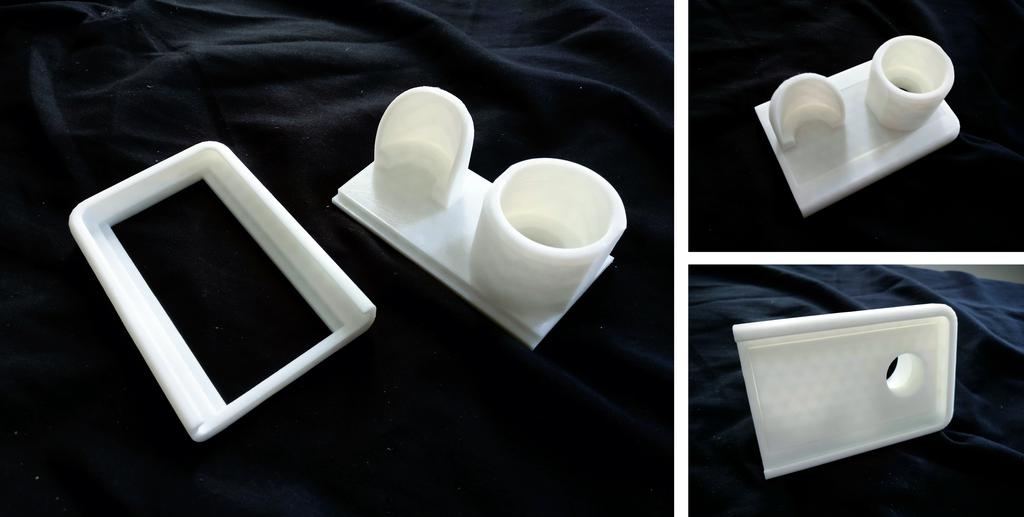
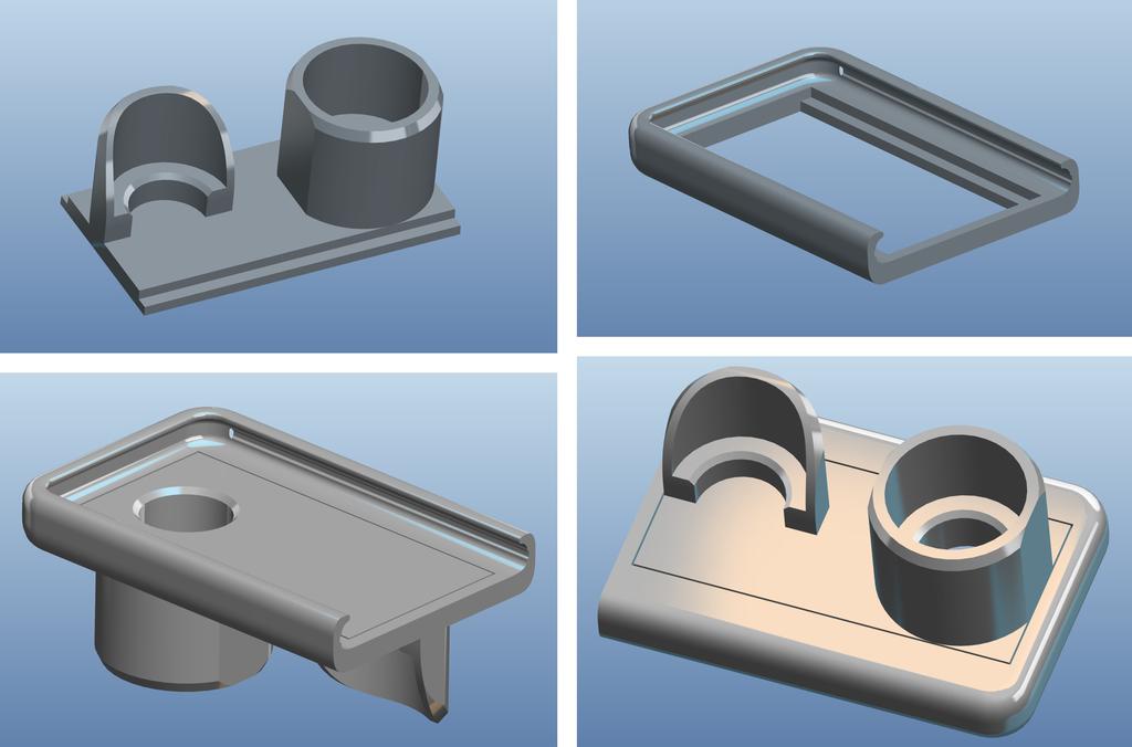
This one isn't universal, but it's much easier to use—sliding the phone into the adapter perfectly aligns the camera with the optical axis of the microscope, at the proper distance away from the ocular to achieve a sharp focus. I designed it with a specific microscope in mind—an Olympus CH30—but made it modular so it'd be easy to adapt to other microscopes. By splitting it into two parts—a phone carrier and a ocular mount—I'd only need to print a new ocular mount to use it with other models. This also made it easier to print, obviating the need for supports as the separate parts are printable without overhangs.
I designed the adapter using PTC Creo in September 2018. If you're interested in downloading it, head over to Thingiverse.
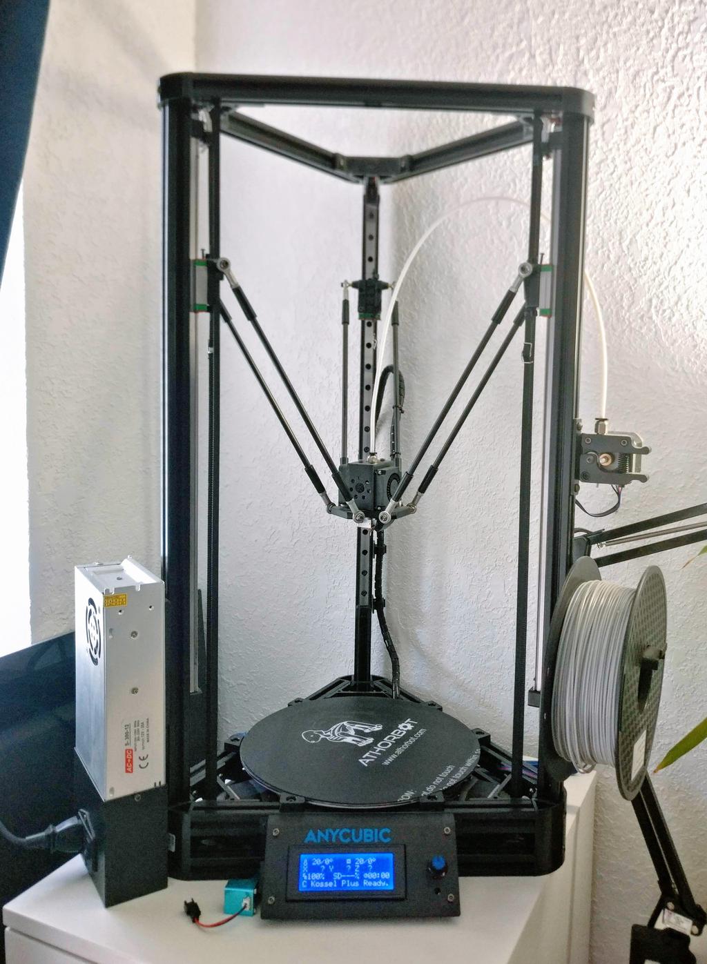
As an aside, this is one of the first prints I've made on my newest printer, an Anycubic Kossel Linear Plus Delta. I bought this recently as a kit from eBay, so that I'd have a second, more compact printer for small-apartment living. It's incredible how cheap high-quality printers have become!
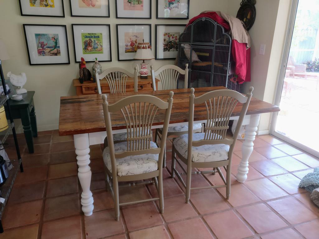
On a never-ending quest to learn to make everything, I bought a used wood lathe on Craigslist. Shortly thereafter, I found a set of lathe chisels at the local flea and was off to the races. Well, not quite. Shortly after that, I found my metal lathe at a garage sale—the tool I was looking for in the first place—and jumped right into using it. And so the wood lathe sat for a while, loved but untouched.
Many months later, I saw this video from Jimmy Diresta, and was inspired. This was right after Hurricane Irma, and the truckload of reclaimed horse stable hardwood that I had used to board up my parent's house, donated by a generous friend, needed to come down. Those boards had the rustic character perfect for project like this; they were worn, partially painted, and discolored by years of sun and rain, but solid.
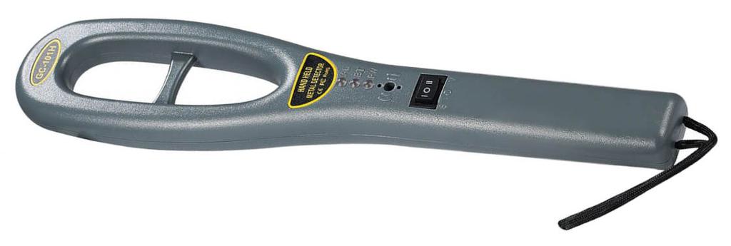
handheld metal detector (exact model no longer available, but you can find similar for less than $20)
Before I got started—and this is important—I pored over them with a hand-held metal detector. Like every piece of reclaimed wood I'd come across, these boards were chock-full of old nails and screws—rusty, eroded, and missing heads—some of which I'd have missed if I had only looked by eye. And I really didn't want to find out about these by hitting them with the tablesaw or router.
I also cut away any rot with the table saw and ran them through the surface planer for a few passes to normalize their thickness (to varying degrees; those used for the top were left nearly untouched to preserve their existing character).
Legs
Most of the boards were either 2x6s or 2x8s (which, depending on the type of wood, vary between 1-1/2 and 2 in. thick), and none were thick enough to turn into legs on their own, so I had to glue several together to create the blank for each leg.
To do this, I binned the boards by grain density (under the assumption that those most-similar in grain density would expand most-similarly between seasons), used a jointer and surface planer to make them flat and parallel for gluing, trimmed the edges with the tablesaw so that the blanks would have the same width and height once glued, and glued them with Titebond III (my go-to wood glue), applying as many clamps as I could manage to ensure a tight bond.
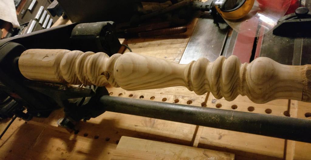
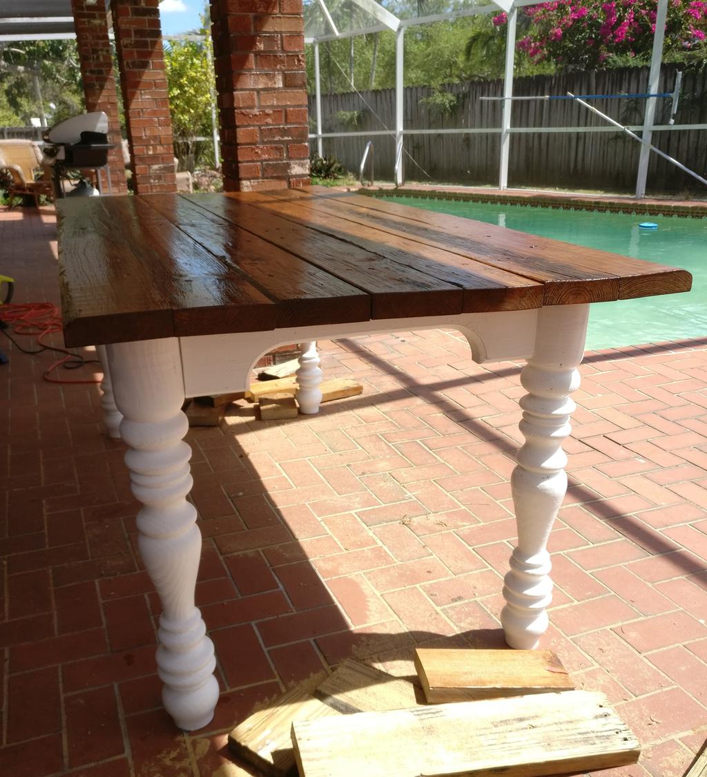
After this, I clamped them into the wood lathe (faceplate on one end, live-center on the other), and began to shape them, free-form. After shaping them into cylinders, but before cutting into them further, I used a pencil to mark roughly where I wanted to make cuts (while they spun), roughly matching each leg to the one before it. They aren't all identical, but I didn't make that a real priority either. After shaping them, I cut a bit off the top and bottom of each to bring them to the correct length, and brushed on a few coats of white satin latex outdoor paint.
first leg, on the lathe
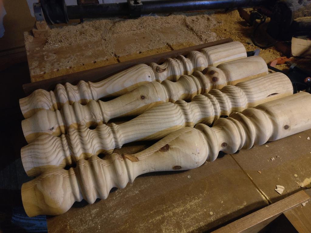
all four legs
Having never used a wood lathe before, here's a few takeaways:
Make sure that the wood lathe is securely mounted to something heavy and steady (or that it's bolted to the ground), and that your part is securely mounted to that, before you start. It doesn't take much imbalance for everything to start jumping around.
Take small passes, especially when you start and your stock isn't cylindrical.
Wear a face shield. Underneath that, wear safety goggles, a mask or respirator, and hearing-protection. Also wear an apron if you have one, and pants that cover your ankles. Half of those are to save your life, the other half are to keep the sawdust away from places it doesn't belong.
Maintain good ventilation, and preferably, use a dust extractor (something I definitely need). You'd be amazed at how cloudy the air can get if you don't.
Give yourself plenty of room to get out of the way if you have to. While turning one of the legs, the faceplate provided to me by the previous owner broke, sending the leg flying through the air. I wasn't hurt, and I somehow managed to catch the leg (so neither was it), but it definitely made me step back and reflect for a bit. Again, always wear safety gear!
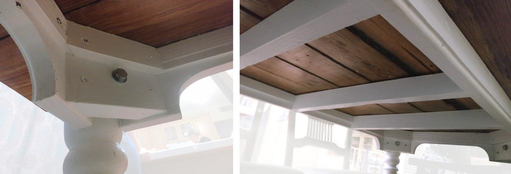
Frame
I didn't stray very far from what Diresta did in the video linked above, so I won't go into too much detail about the frame. I don't have a finish nailer, so I used glue and screws instead, but I did hand-route all of the trim from the same wood as the rest of the table. The frame was painted using the same white satin paint as the legs.
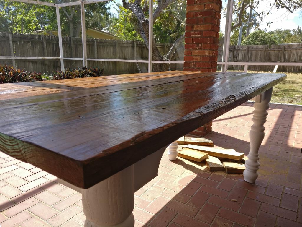
Top
Among the longest of the remaining boards, I picked 7 that were reasonably-flat and that had plenty of character, including two that still had a bit of live-edge (which I would use for the 2 longest edges of the table). Laying these out on a tarp, I applied several coats of Minwax PolyShades polyurethane (with red oak colored stain, to darken and slightly normalize the coloration) to each side with a natural-bristled brush.
After these dried, I arranged them atop the table and screwed them down to the frame. Using a large framing square, I marked a straight line at each end of the top (where I wanted the tabletop to end), and cut the ends square with a circular saw. After applying polyurethane to the newly cut edges, and waiting an additional 24 hours for it to air out, I was done.
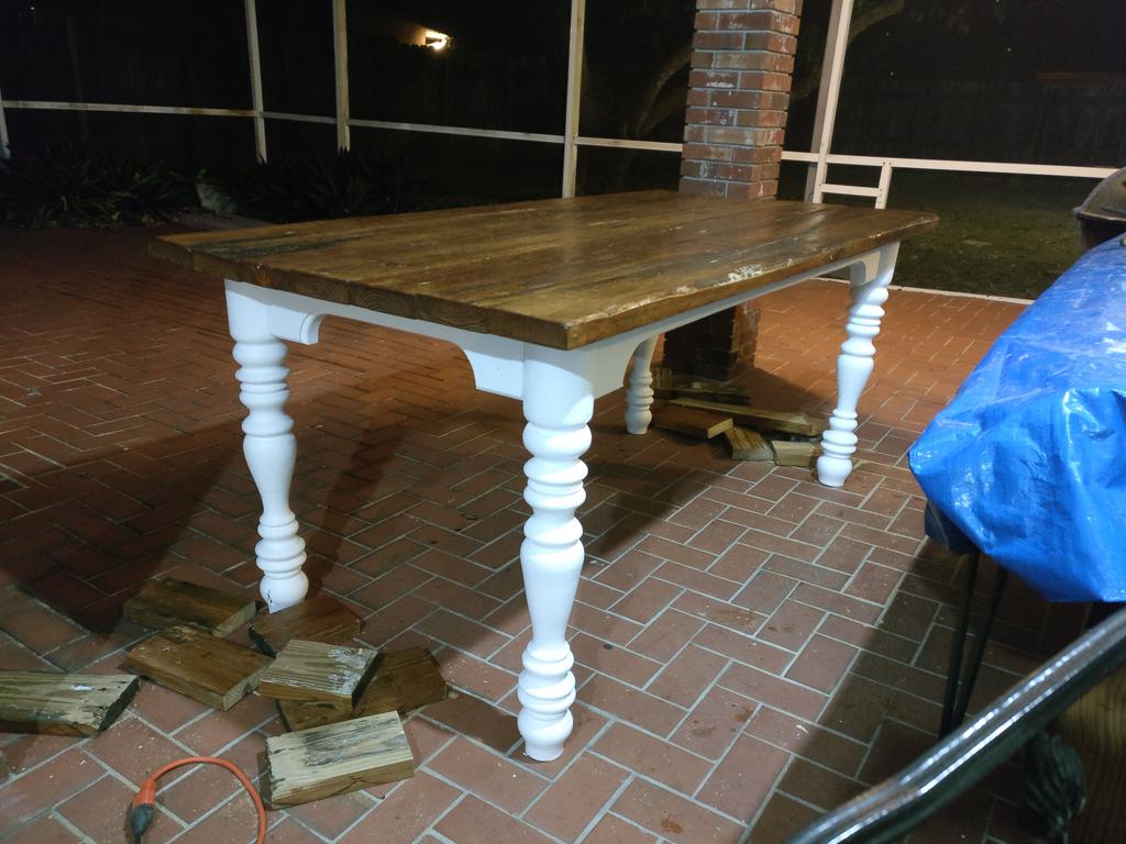
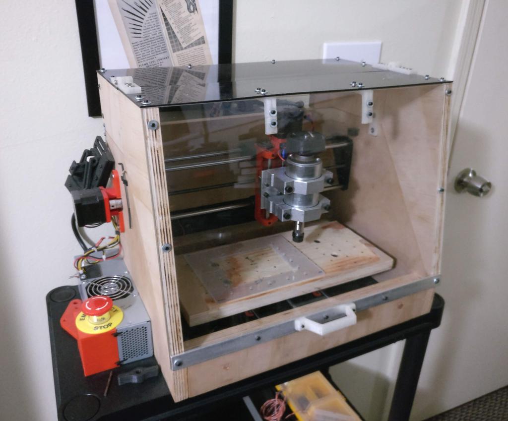
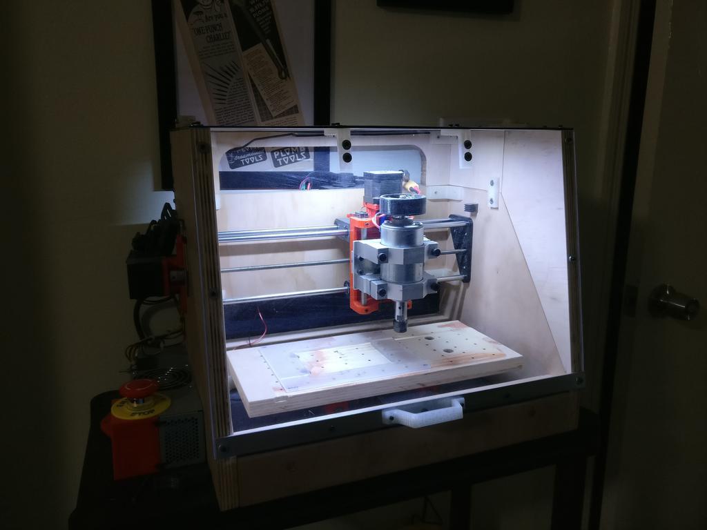
At the moment, I don't have time to write an in-depth post on this, but in lieu of that, here's a bunch of pictures I took while building it. If you're interested in reading more (or have any specific questions), let me know in the comments, and I'll push it further up the to do list.
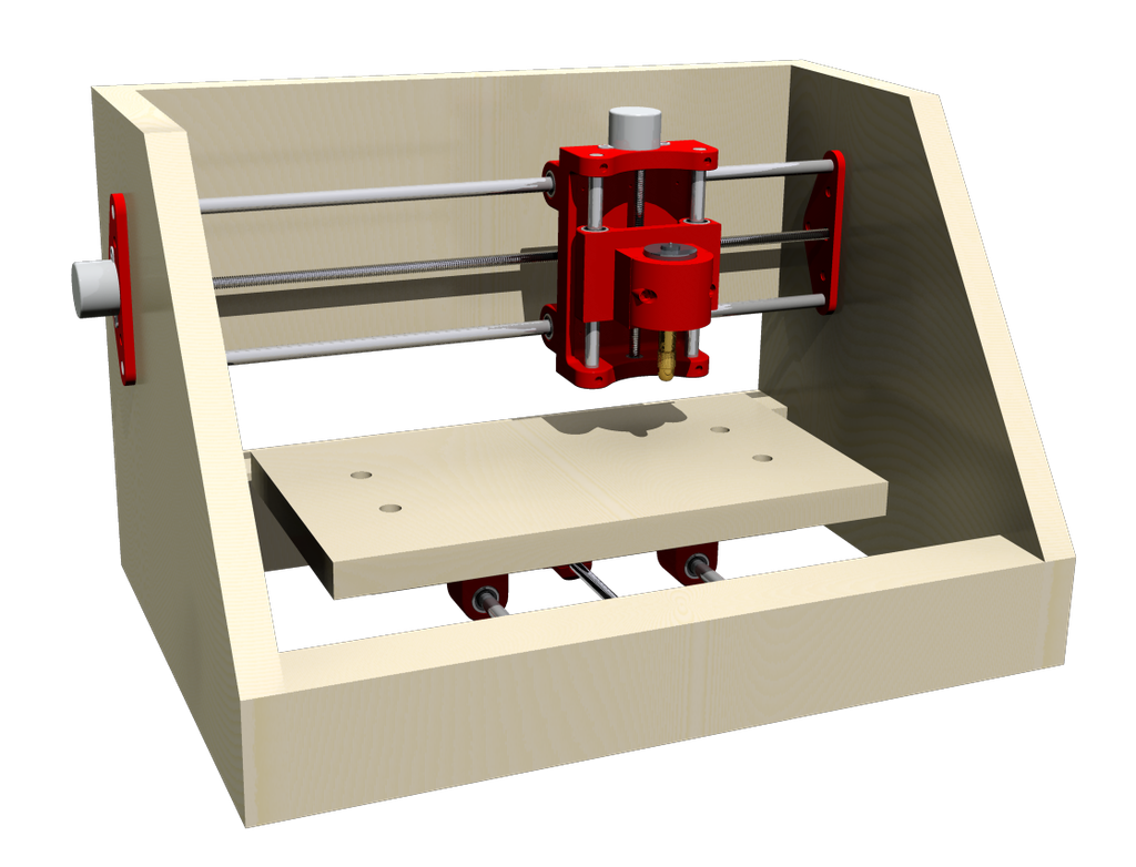
I originally planned to build this small CNC mill for PCB prototyping. While it is capable of being used for that, in retrospect, I'm not sure that spending the time to mill out a prototype PCB is worth it when I can have several professionally-made multi-layer PCBs made and delivered to my doorstep for a few dollars in a few weeks or less. That said, it'll certainly be useful for milling other things!
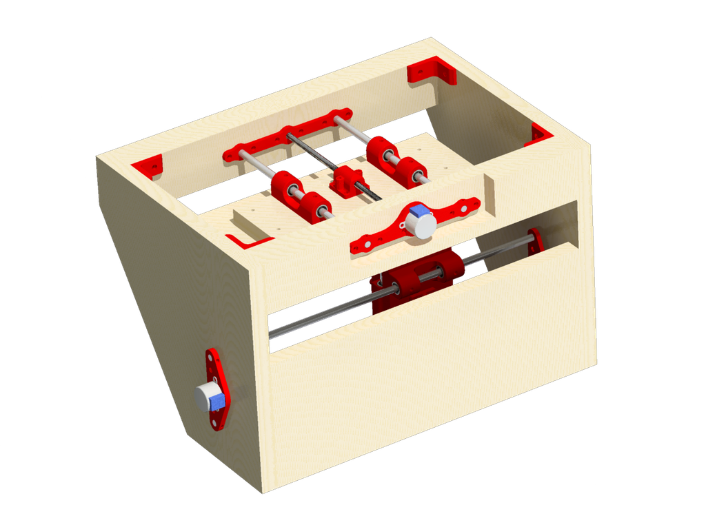
Initial CAD Renderings
At the time, I was planning to use smaller steppers. All parts that are not made of metal or wood are 3D-printed, and all parts were designed in PTC Creo.
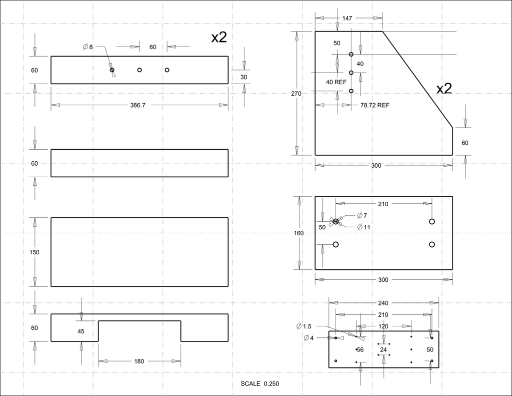
Wood Cuts
Doesn't include the hinged lid, which was added later, or any other modifications made on-the-fly.
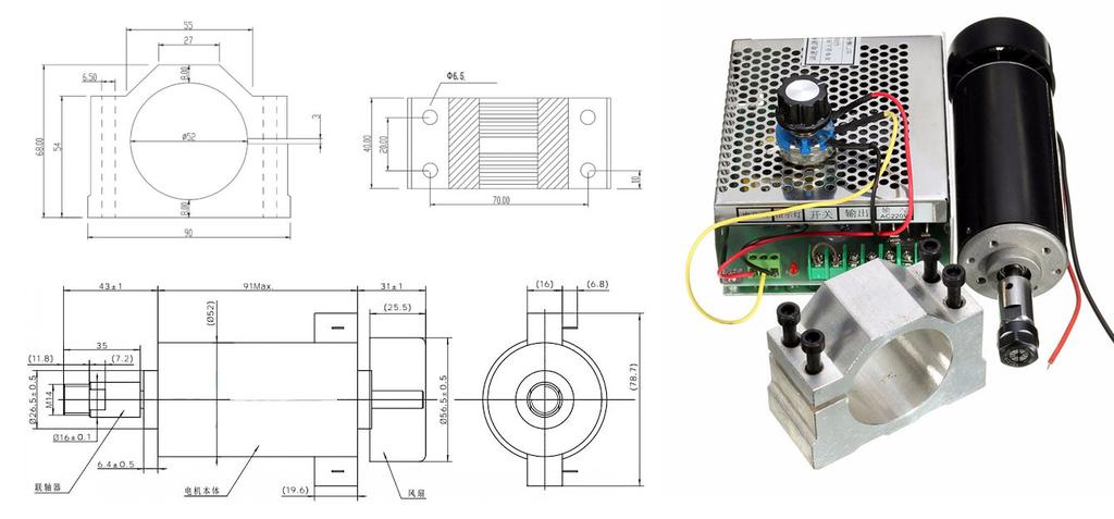
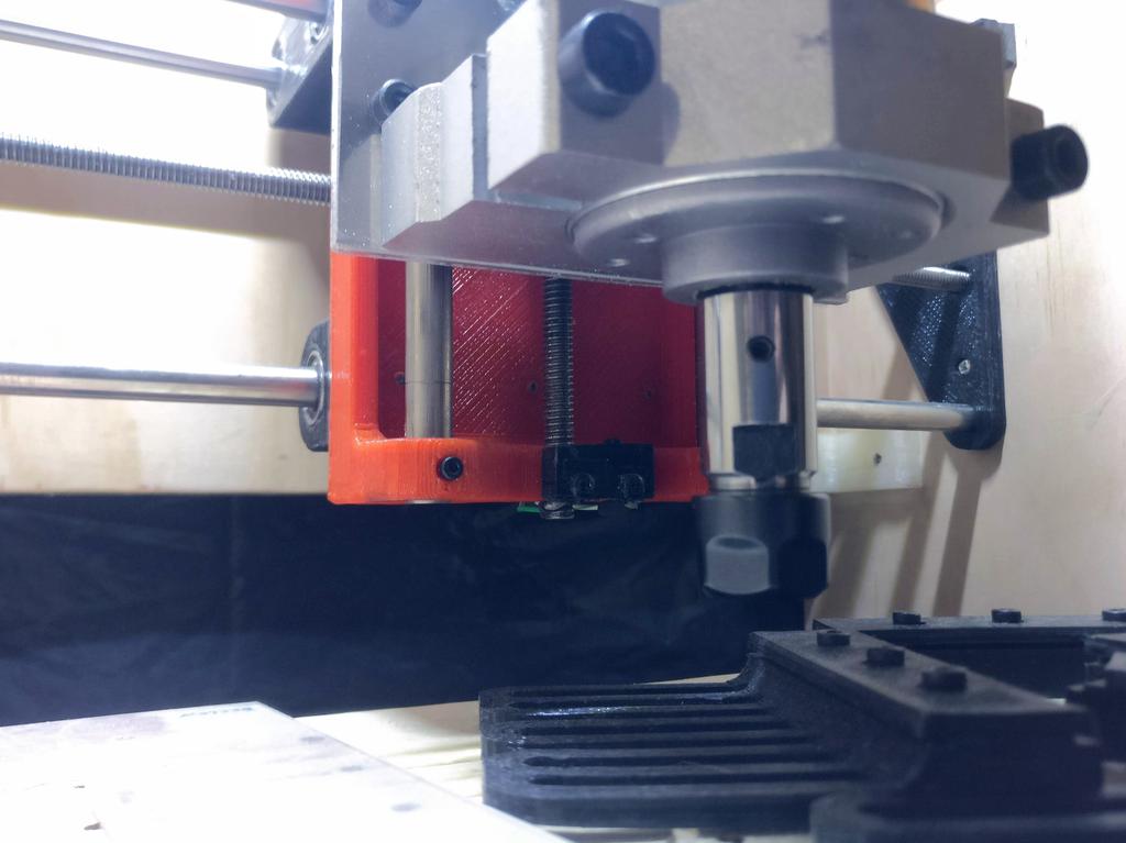
Chinese Spindle Motor
The provided clamp was cut in half, to better support the large motor.
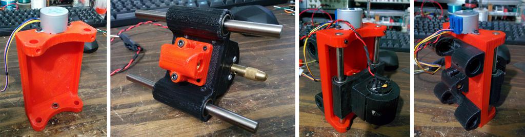
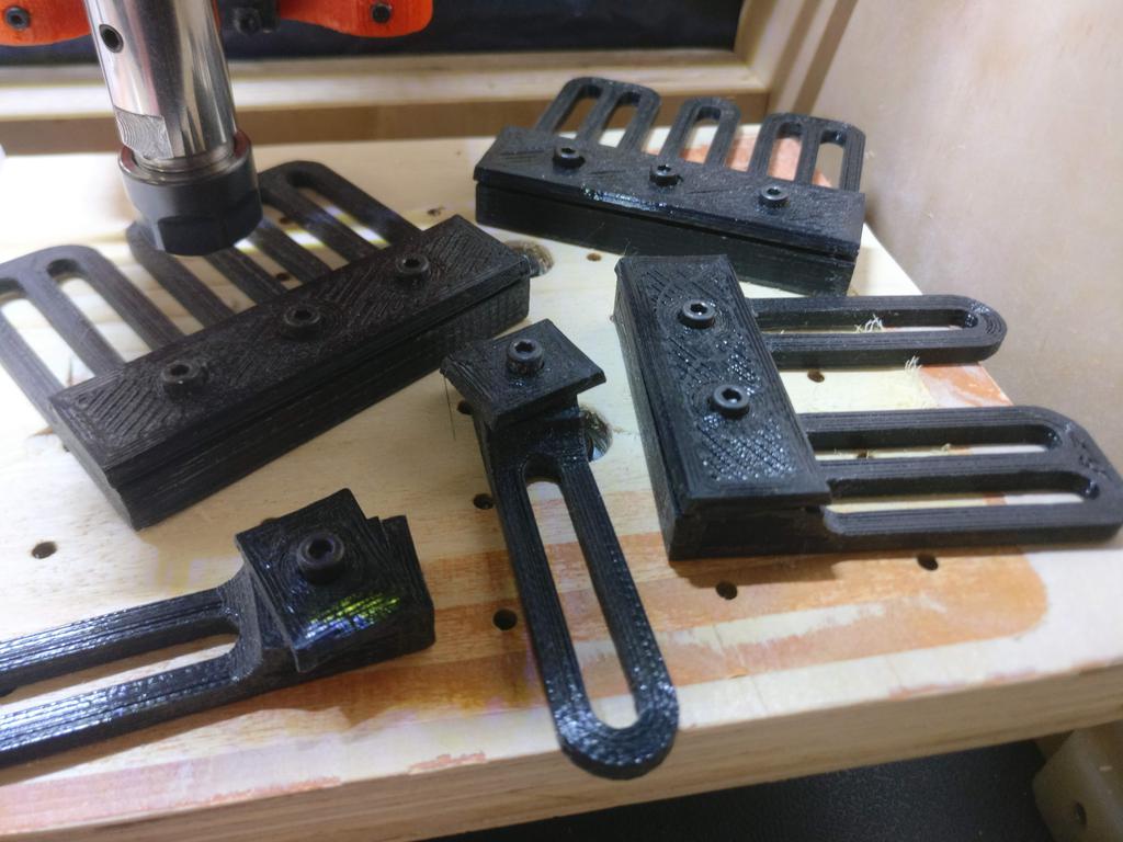
3D Prints and Assembly
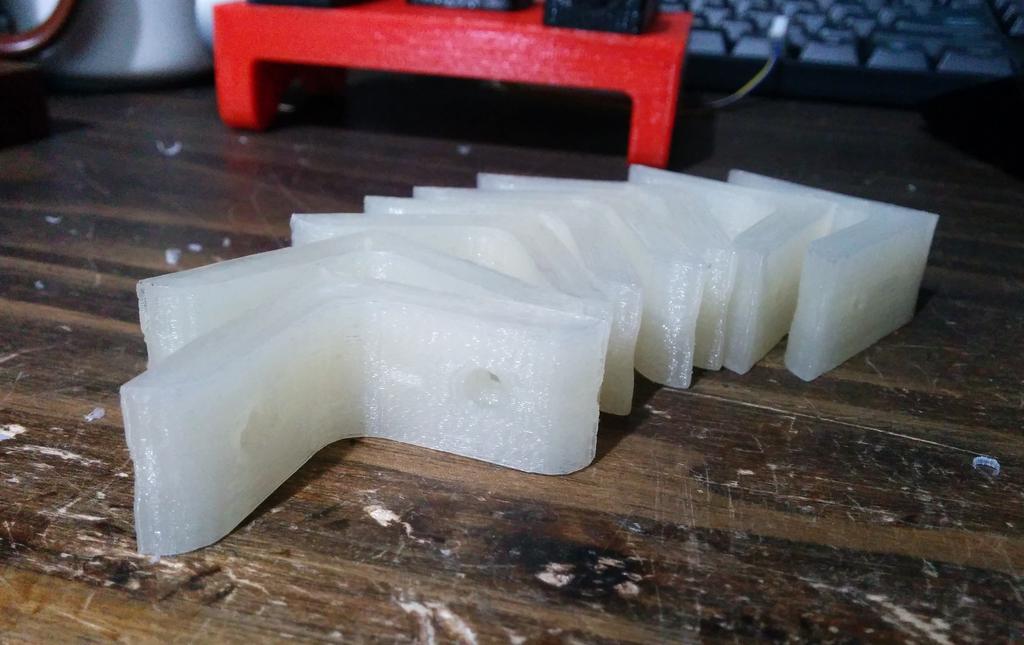
Brackets for quickly assembling and squaring the frame
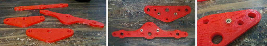
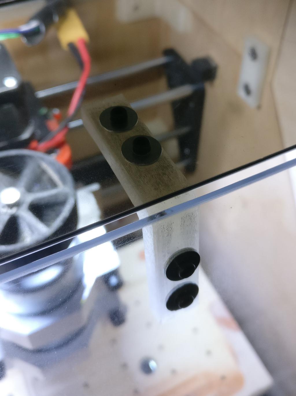
Rod holders and motor mounting plates
Brass threaded-inserts pressed into place using a $5 USB-powered soldering iron (as its tip is small enough to not get stuck).
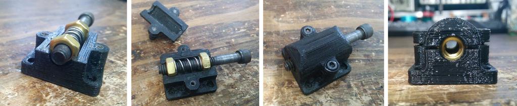
Anti-backlash nuts
The bolt was used only during assembly (in lieu of the threaded rod) to keep the spring and nuts from flying away.
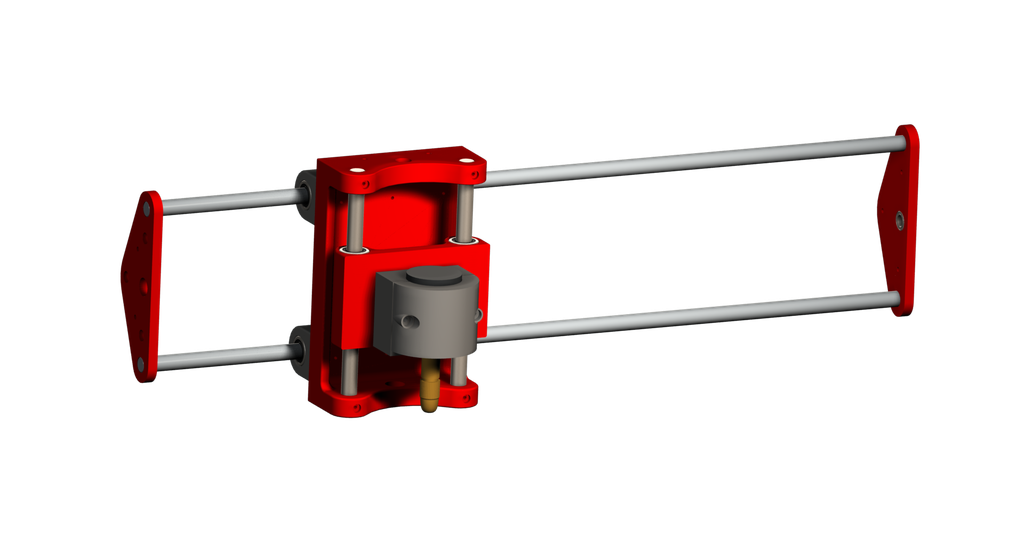
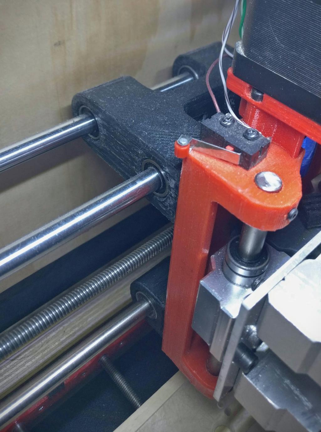
Z-axis assembly, with original (small) stepper motor
Leadscrew not yet mounted.
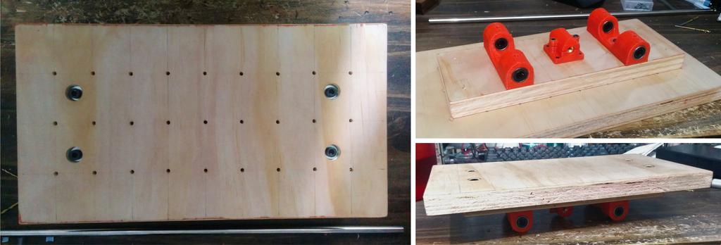
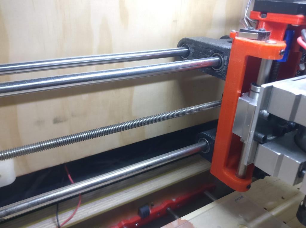
Y-axis, with linear bearing holders and anti-backlash nut
In case you were wondering, the holes in the plate were made using the CNC itself.
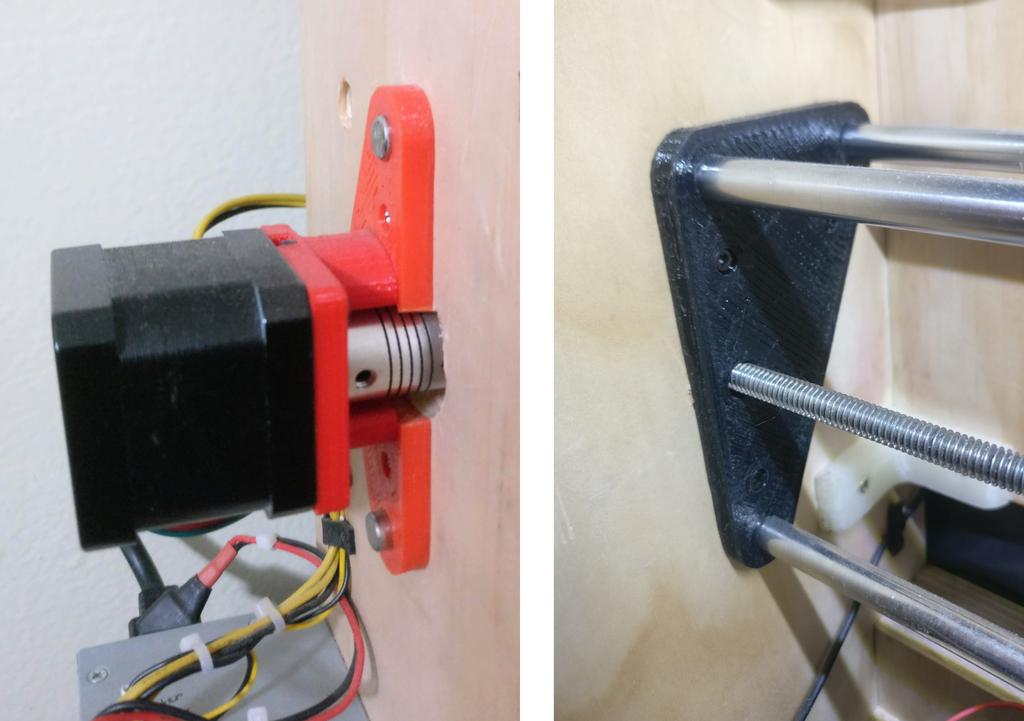
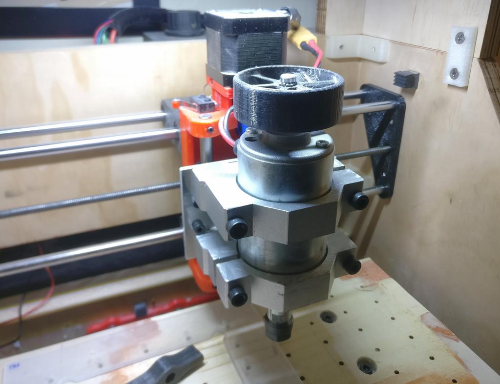
Adapters for larger stepper motors
When switching to larger steppers, I designed adapters for mounting to the motor-mounts that were already installed.
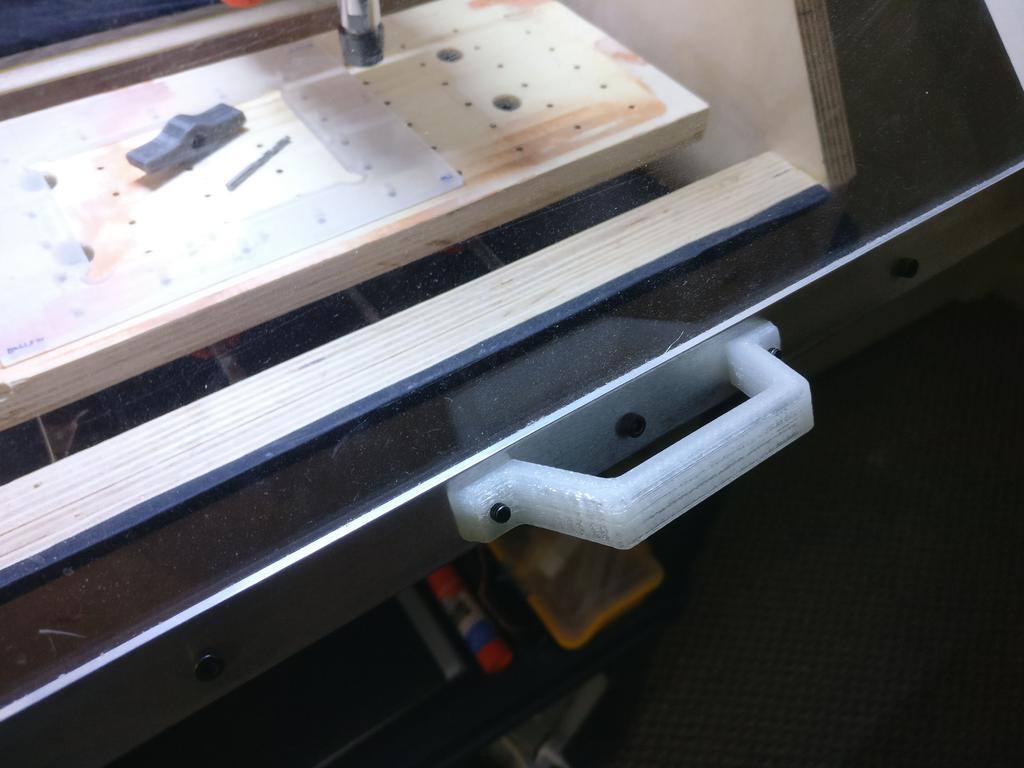
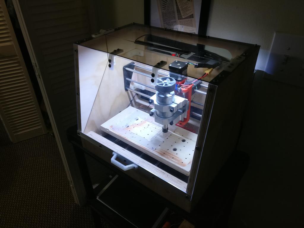
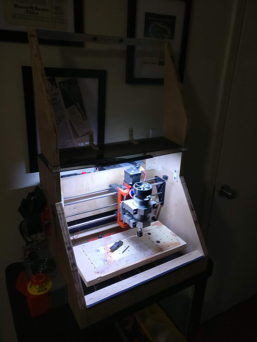
Handle for hinged-lid
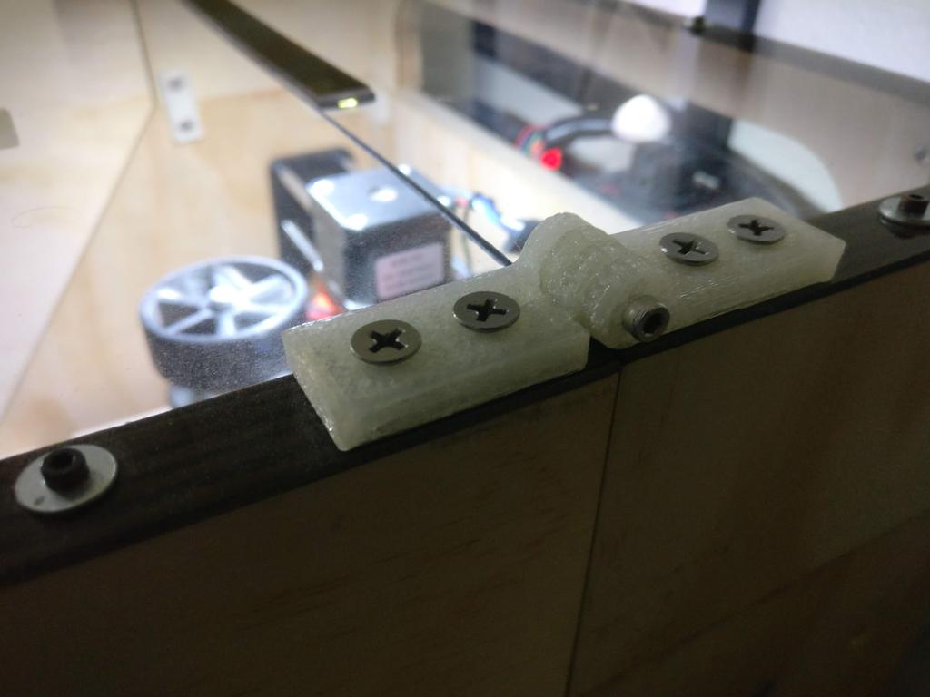
Angle-brackets for stabilizing acrylic windows on hinged lid
Hinges for hinged-lid
A bolt is used as the hinge-pin. For one side of the hinge, the holes are tight, so that the threads bite into it; for the other, they're loose, so that the hinge hinges freely.
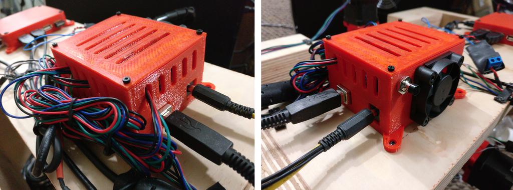
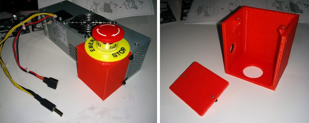
Electronics enclosure and related parts
Original version:
Final version:
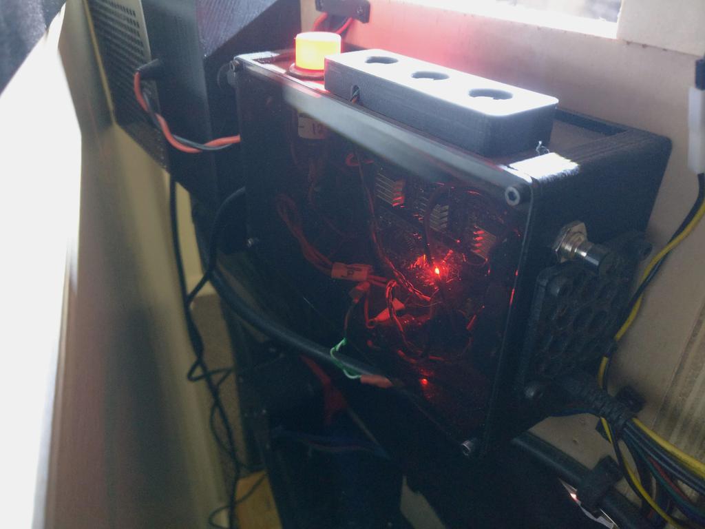
E-stop mount
The emergency stop button is mounted to the power supply. Pressing it directly cuts power to the printer.
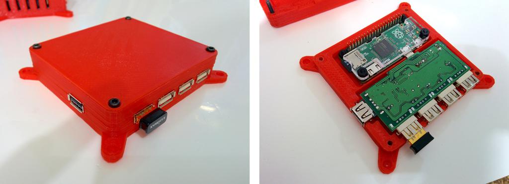
Raspberry Pi Zero and USB hub enclosure
This was eventually replaced by an old laptop; running a headless CNC mill was a bit of a silly idea.
PCB and thin-stock clamps
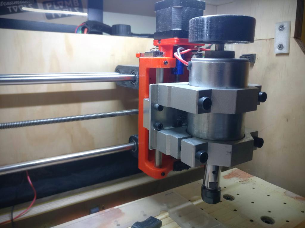
3 rails are better than 2
Okay, I know that 8 mm rails are too thin to expect to prevent deflection; but I had them, so I used them. With only two of them, there was too much deflection, so how about three? Slaps lipstick on a pig.